Contents
Introduction and about the wood sizes
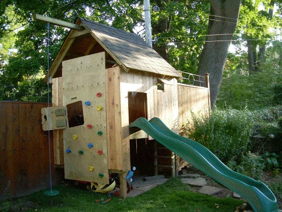
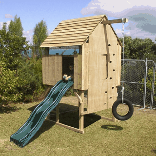
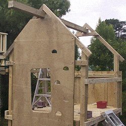
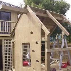
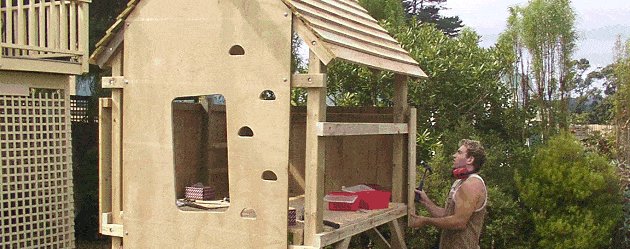
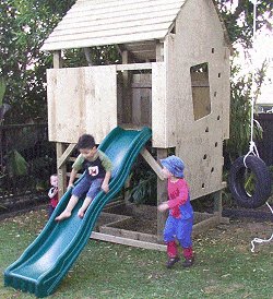
How to build a Kid’s Play Fort
A fort that will provide hours of fun for kids young and old!
This detailed plan-set with step-by-step instructions is in both metric (mm) and imperial (inch) dimensions.
The design includes a trap door entry, a climbing wall, a swing, and there is also a slide installation guide.
The complete frame is fixed together with bolts, so as well as being very strong, the fort can also be dismantled.
The footprint (ground area) is Approx 1800mm x 1800mm (6′ x 6′), and the overall height is 3200mm (10′ 8″).
Floor area is 1500mm x 1600mm (5′ x 5′ 4″), and the floor height is 1300mm (4′ 4″).
Playfort
$5.00About the wood sizes
The dimensions of the lumber used for this project are given in both metric and inches. All dimensions are first written in millimeters followed by feet and/or inches encased in brackets.
Frame lumber sizes (widths and thicknesses) referred to in this project are the approximate actual sizes, that is, the size of the lumber once it has been surfaced (dressed, planed). The actual size is smaller than the nominal size.
For example, if you pop along to the local lumber store and ask for a length of 100mm x 50mm (2″ x 4″) lumber that has been surfaced/dressed on all sides (S4S), the actual finished size will be approximately 90mm x 45mm (1 1/2″ x 3 1/2″).
The table below shows the approximate differences between the nominal and actual sizes of framing lumber. Alternative sizes are mentioned on the next page.
| Metric (millimetres) | NOMINAL SIZE | ACTUAL SIZE | 50mm x 50mm | 45mm x 45mm | 75mm x 50mm | 70mm x 45mm | 100mm x 50mm | 90mm x 45mm | 150mm x 50mm | 140mm x 45mm | 100mm x 100mm | 90mm x 90mm |
| Standard (inches) | NOMINAL SIZE | ACTUAL SIZE | 2″ x 2″ | 1 1/2″ x 1 1/2″ | 2″ x 3″ | 1 1/2″ x 2 1/2″ | 2″ x 4″ | 1 1/2″ x 3 1/2″ | 2″ x 6″ | 1 1/2″ x 5 1/2″ | 4″ x 4″ | 3 1/2″ x 3 1/2″ | |||||||||||||||||||||||||||||
| Metric (millimetres) | ||||||||||||||||||||||||||||||||||||||||||||||||||||||||
| NOMINAL SIZE | ACTUAL SIZE | |||||||||||||||||||||||||||||||||||||||||||||||||||||||
| 50mm x 50mm | 45mm x 45mm | |||||||||||||||||||||||||||||||||||||||||||||||||||||||
| 75mm x 50mm | 70mm x 45mm | |||||||||||||||||||||||||||||||||||||||||||||||||||||||
| 100mm x 50mm | 90mm x 45mm | |||||||||||||||||||||||||||||||||||||||||||||||||||||||
| 150mm x 50mm | 140mm x 45mm | |||||||||||||||||||||||||||||||||||||||||||||||||||||||
| 100mm x 100mm | 90mm x 90mm | |||||||||||||||||||||||||||||||||||||||||||||||||||||||
| Standard (inches) | ||||||||||||||||||||||||||||||||||||||||||||||||||||||||
| NOMINAL SIZE | ACTUAL SIZE | |||||||||||||||||||||||||||||||||||||||||||||||||||||||
| 2″ x 2″ | 1 1/2″ x 1 1/2″ | |||||||||||||||||||||||||||||||||||||||||||||||||||||||
| 2″ x 3″ | 1 1/2″ x 2 1/2″ | |||||||||||||||||||||||||||||||||||||||||||||||||||||||
| 2″ x 4″ | 1 1/2″ x 3 1/2″ | |||||||||||||||||||||||||||||||||||||||||||||||||||||||
| 2″ x 6″ | 1 1/2″ x 5 1/2″ | |||||||||||||||||||||||||||||||||||||||||||||||||||||||
| 4″ x 4″ | 3 1/2″ x 3 1/2″ | |||||||||||||||||||||||||||||||||||||||||||||||||||||||
Required wood and alternative sizes
There are five different lumber sizes used in this project. They are:
- 90mm x 90mm (3 1/2″ x 3 1/2″) for the beam and the four corner uprights,
- 90mm x 45mm (1 1/2″ x 3 1/2″) for the ladder upright,
- 70mm x 45mm (1 1/2″ x 2 1/2″) for the frame,
- 45mm x 45mm (1 1/2″ x 1 1/2″) for the ladder rungs,
- 150mm x 25mm (1″ x 6″) for the roof, walls, and floor
There is also 1 sheet of exterior 18mm x 2400 x 1200mm (48″ x 96″ x 3/4″) plywood required.
All the lumber used in this project is surfaced (dressed, planed) except for the 150mm x 25mm (1″ x 6″), which is rough.
Alternatives sizes
If 70mm x 45mm (1 1/2″ x 2 1/2″) is unavailable in your area, you can rip 140mm x 45mm (1 1/2″ x 5 1/2″) stock in half.
Or alternatively you can use 90mm x 45mm (1 1/2″ x 3 1/2″) stock
If 45mm x 45mm (1 1/2″ x 1 1/2″) is unavailable in your area, you can rip 90mm x 45mm (1 1/2″ x 3 1/2″) stock in half.
If 150mm x 25mm (1″ x 6″) is unavailable in your area, then use the closest size that is available, maybe even decking boards.
If other size lumber is used, or if unsurfaced (rough) frame lumber is used, you will need to make some adjustments to the measurement of the plans to compensate for the size difference.
In all, you will need the following amounts of wood…
Measurements are given in millimeters and (inches). All stock should be suitable for outside use.
- 90mm x 90mm (3 1/2″ x 3 1/2″) surfaced/dressed stock, 5 @ 2400mm (96″)
- 70mm x 45mm (1 1/2″ x 2 1/2″) surfaced/dressed stock, 40 meters (132 ft)
- 90mm x 45mm (1 1/2″ x 3 1/2″) surfaced/dressed stock, 1 @ 2000mm (80″)
- 45mm x 45mm (1 1/2x 1 1/2) surfaced/dressed stock, 6 meters (20ft)
- 150mm x 25mm (1″ x 6″) rough unsurfaced stock, 95 meters (310ft)
- 1 only sheet 18mm x 2400mm x 1200mm ( 4ft x 8ft x 3/4″) exterior plywood
Cutting list and hardware requirements
Cutting List
Sizes in millimeters and (inches)Stock Size Individual Length Used For Total Amount 90mm x 90mm (3 1/2″ x 3 1/2″) surfaced/dressed treated or natural decay-resistant lumber suited for outside use 5 @ 2400mm (96″) beam and corner uprights Total Amount 5 @ 2400mm (96″) 90mm x 45mm (1 1/2″ x 3 1/2″) surfaced/dressed treated or natural decay-resistant lumber suited for outside use 1 @ 2000mm (80″) Ladder upright Total Amount 1 @ 2000mm (80″) 70mm x 45mm (1 1/2″ x 2 1/2″) surfaced/dressed treated or natural decay-resistant lumber suited for outside use 2 @ 1800mm (72″); 4 @ 1690mm (67″); 2 @ 1625mm (64 1/2″); 6 @ 1590mm (63″); 1 @ 1255mm (49″); 6 @ 1200mm (48″); 1 @ 1055mm (42″); 2 @ 630mm (24 3/4); 6 @ 600mm (24″); 1 @ 475mm (19″) Frame 40 meters (132ft) (including wastage) 45m x 45mm (1 1/2″ x 1 1/2″) surfaced/dressed treated or natural decay-resistant lumber suited for outside use 8 @ 570mm (22 1/2″); 2 @ 450mm (18″) Ladder rungs and trapdoor 6 meters (20ft) (including wastage) 150mm x 25mm (1″ x 6″) rough/unsurfaced treated or natural decay-resistant wood suited for outside use 20 @ 1800mm (6ft); 11 @ 1580mm (62″); 2 @ 1200mm (4ft); 36 @ 900mm (36″) Floor and roof/wall cladding 95 meters (310ft) (including wastage) 18mm (3/4″) sheet plywood for outside use 18mm x 2400mm x 1200mm ( 4ft x 8ft x 3/4″) climbing wall 1 sheet
Hardware
- 10mm (3/8″) galvanized coach/carriage bolts with nuts and washers 47 @ 150mm (6″); 6 @ 110mm (4 1/2″); 8 @ 75mm (3″)
- 3kg (7lb) 70mm (3″) flat-head galvanized nails; 0.5kg (1.2lb) 100mm (4″) flat-head galvanized nails
- 4 only 150mm (6″) Galvanized “T” hinges and screws
- 1 only bolt catch or similar for door
- 4 only 200mm (8″) long x 25mm (1″) metal galvanized strap
- 20 only 50mm (2″) long screws to screw the plywood on
- 30 only 18mm (3/4″) long screws for the hinges and pad bolt
- Rope and car tire
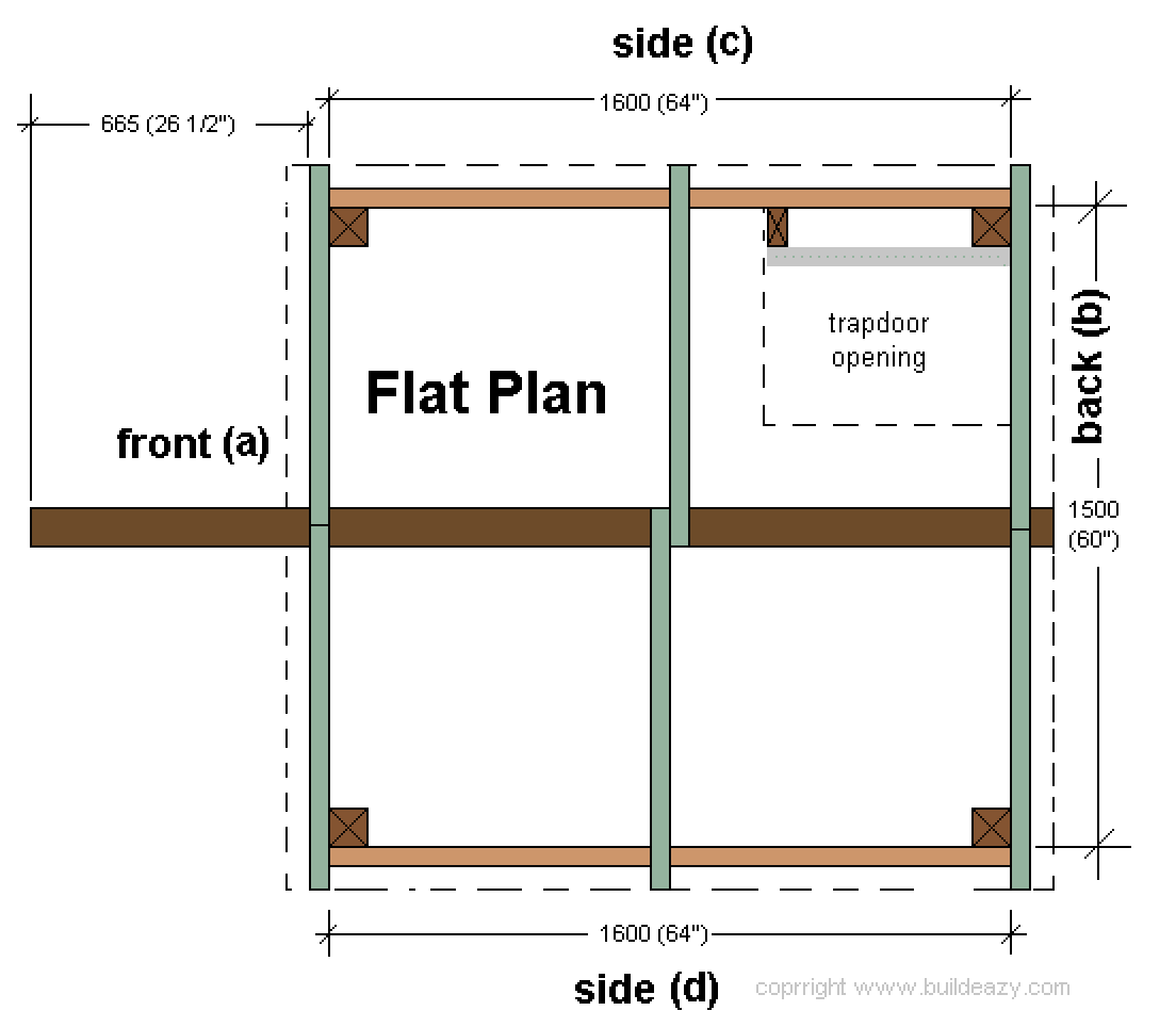
Footprint Plan
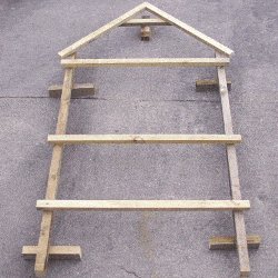
This is the flat plan (footprint), which gives a perspective of the outline and shape from a bird’s-eye view when the wall frames are all bolted together, and shows the position of the roof rafters (in green).
The flat plan also shows the placement of the side frames a, b, c and d which are shown in detail in the elevation plans.
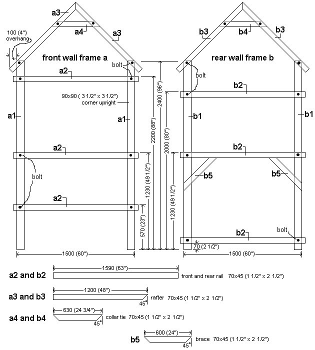
Front and rear wall-frame plans
Below are the front and rear wall-frame plans. This is where the building action starts. Make these two frames up on a flat surface.
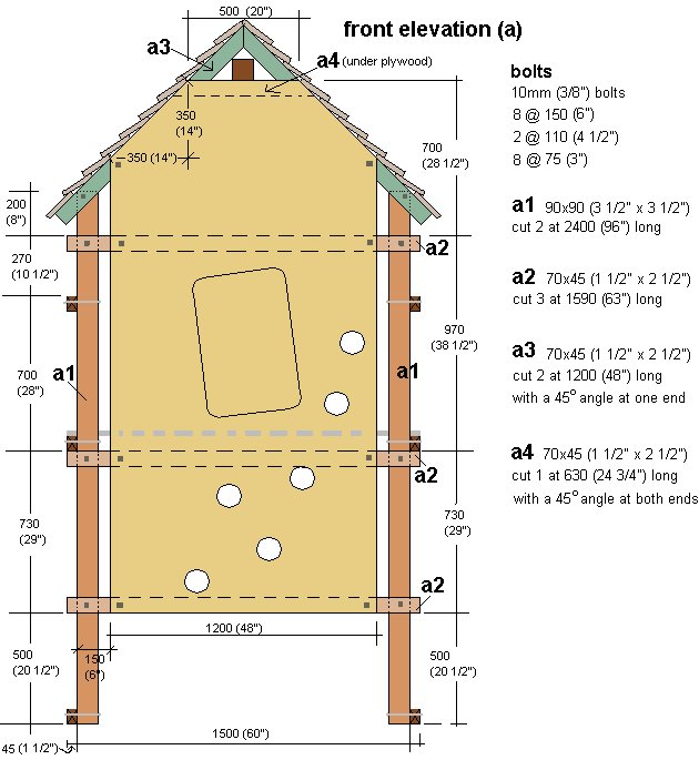
Front elevation plan
Below is the front elevation plan which is basically a view as seen looking to the front of the fort.
This plan also gives the dimensions and other information relevant to the front of the fort.
Rear elevation plan
Below is the rear elevation plan which is basically a view as seen looking to the rear of the fort.
This plan also gives the dimensions and other information relevant to the rear of the fort.

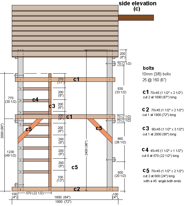
Left-side elevation plan
Below is the left-side elevation plan which is basically a view as seen looking to the left-side of the fort.
This plan also gives the dimensions and other information relevant to the side of the fort.
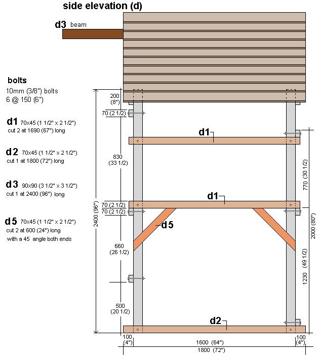
Right-side elevation plan
Below is the right side elevation plan of the play fort which is basically a view as seen looking to the right side of the fort.
This plan also gives the dimensions and other information relevant to the right side of the fort.
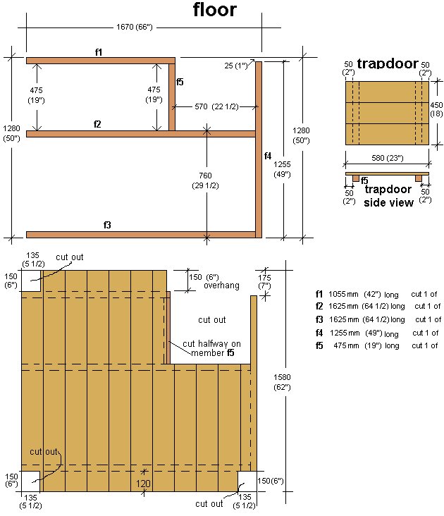
Floor plan
Below is the floor plan of the play fort which is basically a view as seen looking down.
This plan also gives the dimensions and other information relevant to the fort floor and trapdoor.
A pictorial walk through the building process
Below is a pictorial summary of the various steps you will go through when constructing the play fort.
For more detail on any of the steps below go to that particular step in the ‘instructions’ section beginning on the next page (page 12)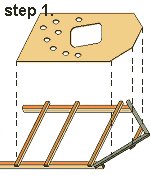
Let’s begin! Instructions step 1
Familiarize yourself with the plans and refer to them as need be. The ‘step-by-step’ pictures on page 11 give a quick pictorial walk through the construction process.
Step 1. Making the front wall
- Make the front frame up on a flat surface.
- Refer to the ‘frame plan’ on page 5 for all dimensions.
- Pack the frame up off the ground (on blocks) so that your hand will be able to fit underneath the frame to put washers and nuts on the bolts, once they are in.
- Hold all the framing pieces together with clamps, and then drill and bolt at every crossing. Refer to the wall frame plan on page 5 for hole placement.
- The two roof rafters can be further secured to each other by placing a piece of galvanized strap over the apex and nailing it to the top of both rafters.
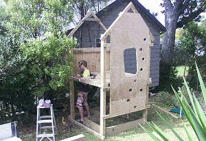
Next, add the climbing wall.
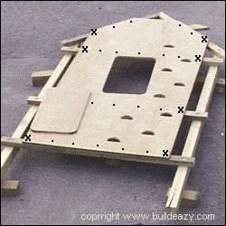
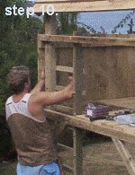
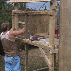
- Lay (centralize) the uncut plywood sheet on the frame. The top of the sheet should be flush (even, line up) with the top of the collar tie. It is easier to cut the openings etc. after the plywood sheet has been fixed to the frame.
- First screw the sheet to the rails and rafters with 50mm screws approx 200mm apart (as shown in photo). Then drill and bolt the perimeter of the sheet to the rails and rafters, approx 50mm (2″) in from the edge of the sheet (as marked with the x in the photo)
- Mark and cut the sheet. Cut off the top corners of the sheet flush with the rafters. Use the front elevation planon page 6 for reference when cutting out the door and climbing holes. The placement of the climbing holes (approx 120mm (5″) diameter) and the door shape, angle and size – approximately 750m x 500mm (30″ x 20″) can be of your own choice. It is a good idea to make the door on an angle (about 7 degrees). Gravity will ensure the door will then always swing open, rather than swing shut and therefore avoid the possibility of jamming little fingers.
- Save the piece cut out of the door hole, as this will become the door.
- Ensure that the frame members are parallel and square.
Instructions steps 2 to 4
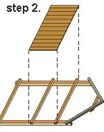
Step 2. Making the rear wall
- Make the rear frame up on a flat surface.
- Refer to the ‘frame plan’ on page 5 for all dimensions.
- Pack the frame up off the ground (on blocks) so that your hand will be able to fit underneath the frame to put washers and nuts on the bolts, once they are in.
- Hold all the framing pieces together with clamps, and then drill and bolt at every crossing. Refer to the wall frame plan on page 5 for hole placement.
- The two roof rafters can be further secured to each other by placing a piece of galvanized strap over the apex and nailing it to the top of both rafters.
- Nail the wall cladding boards to the two rails.
- Have the bottom of the boards flush (even) with the bottom of the middle rail.
- The top of the boards will go above the top rail.
- Ensure that the frame members are parallel and square.
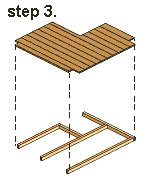
Step 3. Making the floor

- Make the floor up on flat ground, to the dimensions as shown in the ‘floor plan’ on page 10.
- Use the off-cuts from the floorboards to make the trapdoor
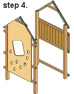
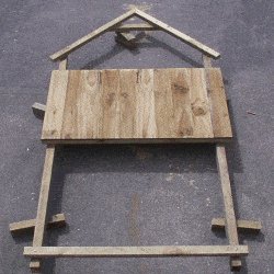
Step 4. Standing the front and rear walls
- Stand the front and rear walls upright.
- You will need help or temporary braces and/or props to hold each end wall vertical until such time as you bolt the side rails in place.
- At this stage, only the middle and lower side rails can be fixed in place until such time as the floor has been installed.
More about that in the next step.
Instructions steps 5 to 8
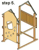
Step 5. Fixing the lower side rails
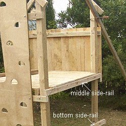
- Bolt the middle and bottom side rails in place. See the picture on the right.
- Do not fit the top side rails until such time as the floor has been installed.
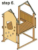
Step 6. Fitting the floor
- The floor will (or should) sit neatly on the rails and will not need further fixing.
- It is simply a matter of picking up the floor and dropping it in.
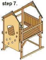
Step 7. Fixing the upper side-rails and the beam
- The two top side-rails (1 each side) can now be bolted in place.
- Make sure all the horizontal frame members (rails) are level and all the vertical members (corner uprights) are plumb (upright) and that the structure is square, and then…… add (nail on) all the diagonal braces except for the one at the corner where the ladder goes (this brace is in the way of a bolt hole and can be added when the ladder is in place).
- Each brace is fixed to the underside of a middle rail and a corner upright.
The beam
- Fix the beam in place ensuring the font and rear walls are parallel. The beam can be fixed to the collar ties each end with nails, and then further secured with metal galvanized strap nailed to both the beam and the collar ties.
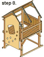
Step 8. Starting the roof, fitting the middle rafters
- Fix the roof boards to ONE SIDE OF THE PLAY FORT ONLY, then make up the middle rafters which are two pieces of 70mm x 45mm x 1200mm (1 1/2″ x 2 1/2″ x 48″) bolted together at right angles.
- Next slide the middle rafters over the beam and under the roof boards. Clamp the middle rafter to the bottom roof board to hold it steady while nailing.
See roof board fixing detail in the next step (step 9.).
Instructions steps 9 to 11
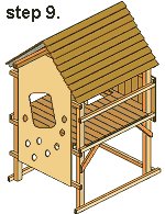
Step 9. Finishing the roof
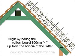
- Now fix the roof boards to the other side of the roof.
So to re-cap…
1). Fix the roof boards to one side of the roof only (see step 8).
2). Insert the middle rafters (see step 8).
3). Fix the roof boards to the other side.
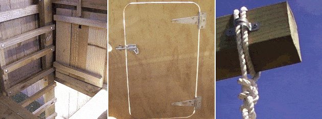
Step 10. Adding the ladder
- Bolt the ladder upright in place and then the ladder rungs.
Refer to the ‘rear elevation plan’ on page 7, and the ‘left-side elevation plan’ on page 8 for dimensions. - The final diagonal brace can now be nailed in place.
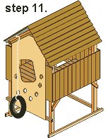
Step 11. Finishing the side walls
- Fix the 150mm x 25mm x 900mm long (1″ x 6″ x 36″ long ) vertical wall cladding boards to the two sides.
- Fix longer boards to each side of the plywood climbing wall.
- Ensure that the top of the side cladding is the same height as that of the cladding on the rear wall.
Instructions steps 12 to 13
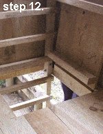
Step 12. Making the trapdoor
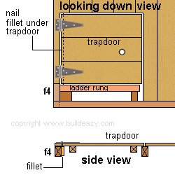
- Make the trapdoor up on a level surface. The trapdoor consists of 150mm x 25mm (1″ x 6″) floorboards nailed to two 45mm x 45mm (1 1/2″ x 1 1/”2) pieces of wood 450mm (18″) long. See the ‘floor and trapdoor plan’ on page 10 for dimensions.
- Next, nail a fillet (an off-cut from a floorboard) to the side of the frame member directly under the hinge side of the trapdoor. This is to give the trapdoor support when people are standing on it. (See side-view picture)
- Lay the trapdoor in place, ensuring that the gap is the same on the hinge side and the opposing side. Screw on two 150mm (6″) “T” hinges, approx 50mm (2″) in from each side.
- Drill a 25mm (1″) finger hole positioned approximately as shown in the illustration
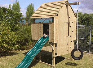
Step 13. The door, the rope and the tire swing
- Almost done. Tie a rope securely to the beam about 100mm (4″) in from the end. Nail some type of bracket or saddle clip over the rope to ensure it is not going to slip off the end of the beam (see picture below). Then tie on a tire to the other end of the rope.
- Fit the climbing wall door in place as shown in the picture below and you’re pretty much done!
Safety concern. If you think the swing could be subject to excessive weight and are concerned about the possibility of the fort tilting, then anchor the opposite end of the fort to the ground. One such method is to concrete a post into the ground at both rear corners and fix the posts to the corner uprights.
Counterbalance for the trapdoor
This will help stop the trapdoor accidentally falling shut and reducing the possibility of a mishap such as the trapdoor falling on heads or fingers while kids are climbing up the ladder.
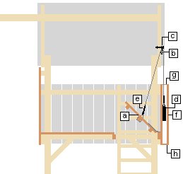
The following is in reference to the drawing on the right.
[a] The trapdoor. There are instructions on how to make the trapdoor in “How to build a Kid’s Play Fort” , however, there will need to be an additional piece of 45mm x 45mm (1 1/2″ x 1 1/2″) wood added to the underside of the trapdoor to give the rope something strong to tie around.
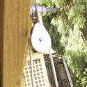
[b] The pulley. The pulley must be able to swing freely and be big enough to take the rope. The pulley must be positioned directly above the casing so the weight will hang vertical. The pulley must not have any parts that a kid can dismantle or undo with hands.
[c] The bolt. The bolt goes through the rafter above the case and supports the pulley. A number of washers and/or shackle/s may be needed to serve the purpose.
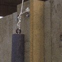
[d] The steel weight. The weight used for this project is a piece of steel 50mm x 50mm x 200mm (2″ x 2″ x 8″) with an eye welded to the top. The weight is about 4 kilo (9lb). Most engineering shops will have a bit of scrap steel lying around that you can generally obtain at a reasonable cost and if you’re willing to pay a bit extra, you should also be able get an eye welded on the top or at very least, a hole drilled through the top. Any shape steel weight will suffice as long as the case is tailor-made to suit the weight.
[e] The rope. The rope must be of a strong and lasting quality. Thread the rope through holes drilled in the trapdoor and around the piece of 45mm x 45mm (1 1/2″ x 1 1/2″) wood underneath, positioned (as shown in the drawings) approximately central lengthwise and about 25mm (1″) in from the edge of the trapdoor on the ladder side. Tie well at both the trapdoor end and the steel weight end and then cover the knots with a PVC adhesive tape so kids cannot undo the knots.
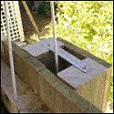
[f] The case. The case is the wood structure made to house the weight. When making the case ensure the cavity is larger than the thickness and width of the steel weight. Bolt the case to the wall directly below the pulley.
[g] Top metal strap. Screw a metal strap (or similar type bracket) across the top opening of the case so that the steel weight cannot be pulled out. Kids will be kids, you know!
[h] Bottom metal strap. Screw a metal strap (or similar type bracket) across the bottom opening of the case so that the steel weight cannot fall out should the rope break or knots come undone.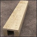

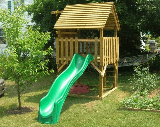
Guide to adding a slide
It is a relatively simple procedure to add a slide to the Kid’s Play Fort.
Put it this way, if you have the skills to build the play fort, then you will have no problem adding a slide!
Purchasing a slide
When purchasing a slide make sure it will be suitable for the Play Fort deck height which is 1300mm (52″) above ground.
The slide in the picture above is a Cool Wave Slide from“Swing-n-Slide”. They offer a lifetime warrantee against cracking or breaking under normal use and the have outlets world-wide. You can get all the info you want as well as installation instructions from their website http://www.swing-n-slide.com/.
There are also many other suppliers around. Shop around. You can enter ‘playground slides’ or ‘kids slides’ into a search engine and see what comes up.
Installing a slide
Your slide will have (or should have) detailed installation instructions with it. It is really just a matter of removing the required amount of wall cladding boards from the play fort where you want the slide to go, and then following the installation instructions that come with the slide.


Hi,
Just a query re the childs play fort. I am in the process of building it now, having purchased plans over the weekend.
I notice that the 4×4 beam across the top is only supported by the two roof apex, a3/4 and b3/4 with additional support provided by the plywood.
Just found myself concerned that the structure may not be strong enough to support the beam plus weight of children and was looking for some reassurance.
Has anyone suggested any additional supports for the roof beam, or had any similar concerns?
Many Thanks. Steve
Reply from BuildEazy:
Hi Steve
Thank you for your query and concern.
I have had the play fort project online for over ten years. A lot of plans have been sold and many forts have been made. I even made three or four myself back then. Over that time I have not received a report of any incident.
Cross piece (a4) is bolted to both A-frame members (a4). The front frame is further strengthened by 3/4″ plywood bolted to the above members. The beam sits on top of cross piece (a4). The structure should be more than adequate to support the beam and a child.
Regardless, precautions should be taken. Ensure that the beam is clear (free of any knots).
The fort should be treated as a playground – with rules and supervision.
Regards, Les Kenny
Hi,
Thanks for the awesome plans!
Enjoy the video – http://www.youtube.com/watch?v=TIlwnIbfPr4
Best, Omer
Hello, I downloaded your plans a couple of months ago and finally finished the project after a few weekends of work.
I used 2×4’s instead of 2×3’s (lumber yard didn’t have 2×3….maybe a US standard), added a lower floor, added supports for the cheap slide, used cedar for top floor and added some slope to the ladder to make it a little easier for my 4yr old.
Your plans were great – very thorough and easy to follow. Thanks for putting the extra effort into adding the English units, adding detailed drawings and materials lists. My daughter already loves it.
Paul
Hello from Hungary (Budapest),
Dear Buildeazy thank you so much for the plans.
As you can see I made some slight modifications and it needs some painting, but the snow came early so I couldn’t finish the paint job.
The kids love it.
Warm regards, F.S.
Hello from Pennsylvania,
I just completed the Kid’s Play Fort.
The design was exactly what I wanted.
The plans were simple and accurate.
I’m the lady with the jigsaw and my friend has the drill.
My grandson loves his new fort.
If granny and her friend can build it, no one should have any problems.
I did change the roof; used plywood and painted it blue with puffy clouds.
Thank you.
Carol Deaver Langhorne, PA
Hello,
I purchased the kids fort design and built a slightly modified fort last summer. I thought you would be interested in seeing the finished project. I found the plans easy to follow and very helpful.
Kindest Regards, Doug Hubble Ontario, Canada
I purchased the Play Fort plans last year and finally completed the Play Fort. My son, who is 9 years old, loves it. I wanted to include a picture of the finished product. Thank you so much for the plans!
Jim Beers Hellertown, PA
Hi,
I went about building the play fort a bit backwards, we were gifted a slide by a friend who was moving. The slide languished in the side yard for a few months when I finally decided to build something so that my kids could use it.
I bought your plans a bit over a week ago and have spent the last week building the kid’s play fort. I’m a novice and found your plans to be perfectly suited for a beginner.
I made a few alterations, I left out the climbing wall (my kids are 2 and 4, I didn’t thing they’d enjoy this yet), extended the shorter wall to make the fort a square (this required a re-do of the floor plan as well, for which I received some much needed advice from a friend in construction), went with some cheap plywood for the roof, and made stairs rather than the ladder (which makes it easier for my 2-year-old to get up). All-in-all I’d say it turned out pretty great and the kids love it.
Thanks!
Mark Sheen (Phoenix, AZ)
Just completed “Playfort with climbing wall”
Many thanks
James (Christchurch, New Zealand)
Many thanks.
Just wanted to let you know the fort has been built and played with for over a year now, with one or two amendments to the plans:
• Slide and ladder at the front with a small climbing wall up to the trapdoor
• Swing beam added on one side to allow a pulley connected to the front as well.
• With the exception of the roof, 4×2 used in place of 3×2.
But all concerns re structure and strength have been put to rest with four adults having picnics on the fort.
Thanks again
Steve Layzell
I just bought the plans for the Raised Play Fort by Les Kenny and wanted to know how holds up in the wind.
Do you have any information regarding this issue?