Contents
Introduction – Plans and individual pieces
Introduction (scroll down for Plans)
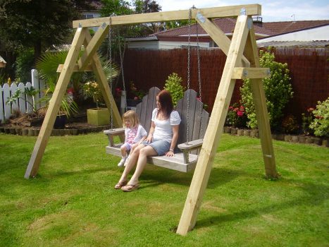
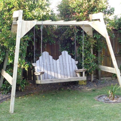
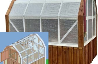
The footprint (ground area) of this swing seat support frame is 2700mm (9ft) x 2100mm (7ft).
The overall height is 2025mm (81″).
Although this support frame is purpose-made for a particular swing seat, it can also be used to support numerous other utilities such as swings or maybe a glide-ride, and is even capable of accommodating certain types of gym equipment.
It is a very solid frame and basically consists of two end A-frames designed to minimize front and back movement, a beam which sits on top and two braces designed to minimize sideways movement.
The lumber used in this project is 100 by 100 (4×4) stock, which means that the lumber is 100 millimeters (4″) wide by 100 millimeters (4″) thick. This is a very common stock size and should be readily obtainable from most lumber or building supply yards. If you prefer to use smooth lumber as opposed to rough, that generally means that the wood has been planed or dressed and therefore the size of the lumber will be slightly smaller, but that does not matter. Most important is that the lumber is suitable for outside use and strong enough for the job, which basically means the stock should be reasonably straight-grained and contain very few knots – definitely no big knots. Your local lumber supplier will be able to advise you on the most suitable types of lumber available and also what safety precautions might need to be taken while working with any particular type of lumber. For example, when working with treated lumber you will need to wear appropriate clothing, gloves and mask while cutting or shaving and certain waste disposal and clean up rules must be adhered to.
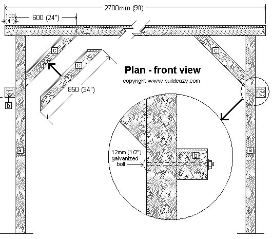
Below are the plans followed by a description of each member.
Individual pieces
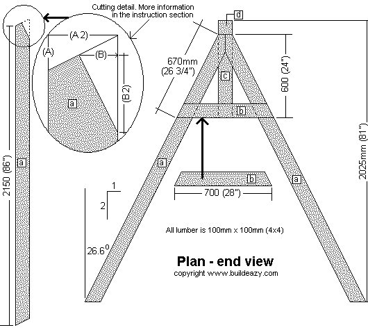
[a] A-frame leg 100×100 (4×4) stock suitable for exterior use. Cut 4 pieces to length as shown above. Angle cut each end 26.6 degrees off square. There is more information on how to mark and cut the angles in the instruction page.
[b] Horizontal brace 100×100 (4×4) stock suitable for exterior use. Cut two pieces to length as shown above. Angle cut each end 26.6 degrees off square.
[c] Diagonal brace 100×100 (4×4) stock suitable for exterior use. Cut two pieces to length as shown above. Angle cut each end 45 degrees off square.
[d] Beam 100×100 (4×4) stock suitable for exterior use. Cut one piece to length as shown above.
Materials list – Fastening detail
You will need…
All the lumber listed below is 100×100 (4×4) stock and should be suitable for exterior use.
- 4 pieces at 2400 (8ft) long. Cut the legs from this.
- 1 piece at 2700 (9ft) long. For the beam.
- 1 piece at 3000 (10ft) long. Cut the braces from this.
You will also need….
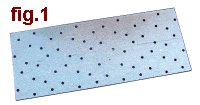
- Galvanized nail-on plate. 2 at 100×100 (4×4); 10 at 125×50 (2×5); 2 at 150×50 (2×6).
- All of the above can be cut out of bigger size plates if necessary.
- Four 12mm (1/2″) galvanized bolts 220mm (8 3/4″) long.
- Two 10mm (3/8″) galvanized bolts 150mm (6″) long. To hang the swing seat chain off.
- 140 50mm (2″) flathead galvanized nails.
- A handful of 100mm (4″) galvanized nails.
Fastening detail
- Use galvanized nail-on plate or similar, to securely fasten all the frame members to each other.
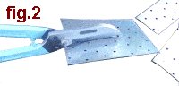
- The sizes listed above can be cut out of larger pieces with a pair of tin snips or other type of plate cutters. See fig.1 and fig.2
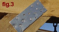
- Fix the plates as shown in fig.3 with five 50mm (2″) flathead galvanized nails into each member. That is, ten nails for each nail-on plate.
Making two galvanized U-shaped nail-on-plates
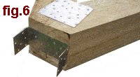
- The top of each “A” frame requires a U-shaped nail-on plate as shown in fig.6.
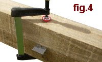
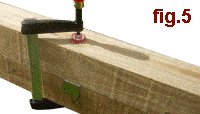
- Each U-shaped plate can be made by clamping a 150×50 (2×6) nail-on plate between two 100×100 (4×4) pieces of lumber (fig.4) and then by hammering down the parts that jut out, as shown in fig.5.
- Each U-shaped plate can then be fixed to the top of the two “A” frames (as shown in fig.6) with 50mm (2″) flathead galvanized nails.
Other Fastening
- Use 12mm (1/2″) galvanized bolts 220mm (8 3/4″) long to fasten the horizontal braces to the legs.
- Use 100mm (4″) galvanized nails to secure members together where needed.
- Use two 10mm (3/8″) galvanized bolts 150mm (6″) long to hang the swing seat chain off.
Instructions
Step 1. Cut all the members

- Cut all the members to length and with the angle cuts as described in the Individual Pieces (Page one).
- All the lumber used is 100×100 (4×4) stock and all the angle cuts are 26.6 degrees off square except for the two diagonal braces which are cut at 45 degrees both ends.
- There are directions below on how to make the angles if you do not have any type of angle marking tool.
- fig.7 shows the cut lines at the top of the legs. fig. 9 below shows how to mark the cut lines at the top of the legs and fig.8 shows how to mark the cut lines at the bottom of the legs.
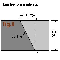
How to mark the 26,6° cut line at the bottom of the legs
(1) Square a line from x to y (fig.8) across the leg.
(2) Mark point z along the leg. The distance from z to x should be exactly half of the distance from x to y.
For example: if the distance from x to y is 100mm (4″), then the distance from z to x should be 50mm (2″).
(3) Draw a line from z to y. This is the cut line and is 26.6° off square.
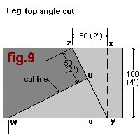
How to mark the 26.6° cut lines at the top of the legs
(1) Square a line from x to y (fig.8) across the leg.
(2) Mark point z along the leg. The distance from z to x should be exactly half of the distance as that from x to y.
For example: if the distance from x to y is 100mm (4″), then the distance from z to x should be 50mm (2″).
(3) Draw a line from z to y.
(4) Mark point u 50mm (2″) from z along line zy. See fig.9.
(5) Square a line from u to v (fig.9) across the leg.
(6) Mark point w. The distance from w to v should be exactly twice the distance as that from u to v.
(7) Draw a line from w to u. This line should be at right angles to line zy.
Instructions continued
Step 2. Lay the legs on stools
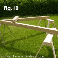
- Lay a pair of legs out in “A” frame position on three stools or supports. See fig.10.
- Position the horizontal brace on top of the two legs.
- The bottom of the horizontal brace should be 600mm (2ft) down from the top of the “A” frame.
- Refer to the plans on page one for more positioning dimensions.
Step 3. Fix the “A” frame
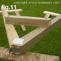
- When the “A” frame members (two legs and one horizontal brace) are correctly positioned, they can then be secured together.
- Use a 100×100 (4×4) nail-on plate where the two legs join and fix a U-shaped nail-on plate to the top of the “A” frame. See fig.11. Also see making a U-shaped nail-on plate (Page two)
- Use galvanized bolts to fix the horizontal brace to the legs, one at each meeting.
- Hold the horizontal brace to the legs with a couple of clamps prior to drilling the bolt holes.
Step 4. Add a brace
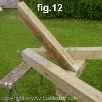
- Fasten a diagonal brace to the horizontal brace of the “A” frame as shown in fig.12.
- Secure with a couple of 100mm (4″) galvanized nails and a nail-on plate.
- Next make up the second “A” frame BUT WITHOUT ADDING THE DIAGONAL BRACE, as that brace will be added when the (almost) complete frame is standing upright.
Instructions rest and end
Fix the beam to an “A” frame
- Tilt an “A” frame against the beam in a sort of a 3-sided pyramid shape so that the beam, “A” frame top and diagonal brace all align.
- Ensure that the top end of the beam is overhanging the “A” frame by 100mm (4″) and that the beam is at right angles (90°) to the “A” frame. Refer to the plan (Page one) if necessary.
- Then, fix the beam to the “A” frame with galvanized nail-on plates. See fastening details (Page two) and fig.13.
Stand the frame upright
- Stand the frame upright and balance the beam on the top of the other “A” frame with the beam overhanging 100mm (4″). See fig.14.
- Ensure that the beam is at right angles (90°) to the “A” frame and then secure by nailing through the U-shaped nail-on bracket into the beam.
Add a brace and make secure
- Add the diagonal brace and fix in place with 100mm (4″) galvanized nails and nail-on plates. See fig.15.
- For further reference on fixing and nail-on plates go to fastening details (Page two).
Attach the seat chain
- Now it’s just simply a matter of hanging the swing seat.
- Insert two 150mm (6″) bolts through the beam above the swing seat, one at each end.
- The bolts will protrude above the top of the beam by about 50mm (2″).
- A chain link can then be fitted over each bolt shank on top of the beam and held in place with washers and nuts. See fig.16.
For plans and instructions on how to make a swing seat:


I don’t see where the bottom of the diagonal brace is attached to the horizontal brace.
if you look at fig 12, it appears they just threw a strap underneath to attach the diagonal brace. i’m constructing one of these this weekend and plan on notching the diagonal brace end instead of cutting it clean so that there is a part of it that rests on top of the horizontal brace as well. not only will that look better but will also provide more stability
Hi..Great idea. that doesn’t change the 45 degree angle on brace or top support, am I right in thinking that?
Would this hold my honey and I ? I’m 5’4″ and 139lbs, and he’s 6’7″ and 245lbs. Also, would it fit him if he sat on it ?