Contents
Build – dismantle – move- reassemble
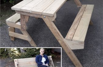
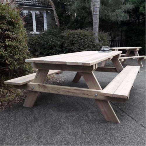
This 8-seater picnic table can be dismantled and re-assembled in 5 minutes (simply eight bolts to take out and put back). It can even be put down into a flat pack of sorts, put into a small car (hanging out the back), moved and reassembled.

You can also purchase this plan:
- 🛑 No ads
- 🖨 Printable PDF
- 🎗Support the author
Make a Wooden Picnic Table that is Easily Disassembled
Original price was: $5.00.$3.00Current price is: $3.00. -40%
|
The size of the thing
Overall it’s 67″ (1700mm) wide by 79″ (2000mm) long and stands 30″ (760mm) high. The tabletop area is 33″ (840mm) wide by 79″ (2000mm) long. That’s a decent size tabletop.
So you see, if it weren’t able to be dismantled easily, it would be a big table to lug around and impossible to get into some places.
I designed this one so I could get it through a narrow garden gate to a back patio. I’m sure a lot of people have a big picnic table and are limited to where they can put it or take it because of its bulk. Not this one. It’s simply a matter of easily undoing 8 bolts, and down she comes. It is in five easily managed sections.
The magic is in the design – incorporating appropriate screws where needed and double horizontal rails at each end. It is very solid without the need for any braces. The side frames, seats, and table are all made independently of each other and designed to be easily bolted (or unbolted) together. Pull it apart and put it back together again in no time at all.
I made the rails out of 2×4 (50 x 100mm) rough-sawn wood because it’s cheaper and a bit meatier than its dressed (planed, dimensioned) counterpart.
I used dressed 1-1/2″ x 5-1/2″ (38mm x 140mm) stock for everything else.
Materials List
2×4 (50 x 100mm) rough sawn wood:
- 2 @ 66-1/2″ (1690mm) for the lower rails
- 4 @ 33″ (840mm) for the top rails and tabletop supports
- 4 @ 12″ (300mm) for the seat supports
In all 30ft (9m) of 2×4 (50 x 100mm) rough sawn wood, allowing for a bit of waste.
1-1/2″ x 5-1/2″ (38mm x 140mm) wood
- 4 @ 38″ (960mm) for the legs
- 10 @ 79″ (2000mm) for the tabletop and seat boards
- 1 @ 33″ (840mm) for the table middle support
- 2 @ 11″ (280mm) for the seat middle supports
In all 90ft (27m) of 1-1/2″ x 5-1/2″ (38mm x 140mm) wood, allowing for a bit of waste.
You will also need:
- 40 of 5″ (125mm) galvanized bugle head batten screws (these big screws are what give the table its strength, stops wobble, and are a crucial part of the design)
- 44 of 3″ (75mm) exterior wood screws
- 8 of 3-1/2″ (90mm) galvanized nails – just to hold the support pieces in while you turn the tabletop over so they can be screwed from the other side.
1/2″ (12mm) galvanized coach/carriage bolts with nuts and washers
4 @ 4″ (100mm)
4 @ 5″ (125mm)
4 @ 6″ (150mm)
Check the lengths if the lumber you get is a different size
Plans: End frame plan and individual pieces

Plans: Seat plans

What gives the table its bracing?
The strength of the table is in the screws and bolts effectively designed to compensate for the typical diagonal wood bracing normally found in similar type picnic tables. That along with the two horizontal members each end – make a very solid table.
The use of 5″ (125mm) galvanized bugle head batten screws as shown below (or similar) and placed as shown in the plan drawing above, firmly holds the table and seat support pieces to the table and seats, and when the end frames are bolted to the table and seat support pieces, ‘wobble’ is eliminated making for a very sturdy picnic table while allowing it to be easily dismantled and reassembled.

A birds-eye-view perspective plan in the next section also shows the screw placement.
Plans: Birds-eye-view perspective

The ‘Birds-eye-view perspective’ is to give another view of the screw placement using 5″ (125mm) galvanized bugle head batten screws or similar.

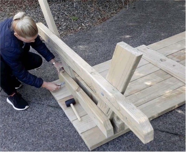
Step. 1 Make the end frames
Cut the pieces for the end frames to the dimensions and shape as shown in the “Plans: End frame plan and individual pieces”.
In all, there are 2 top rails, 2 lower rails, and 4 legs.
Once cut, lay the pieces out and position them as shown in the drawing below. The dimensions are in the plans “End frame plan and individual pieces”.
The top rails:
Glue and screw the top rail to the legs as shown in the ‘End frame plan’. Drill 9/16″ (13mm) bolt holes through the middle of where the top rail and leg cross.
BUT DO NOT PUT IN THE BOLTS for the time being.
The lower rails:
Glue and screw the lower rail to the legs as shown in the ‘End frame plan’. Drill 9/16″ (13mm) bolt holes through the middle of where the lower rail and leg cross, insert a 1/2″ (12mm) galvanized coach/carriage bolt in each hole, add washers and nut and tighten.

Step. 2 Make the seats and table
The table consists of 6 tabletop boards, two table support pieces, and one tabletop middle support piece.
Each seat consists of 2 seat boards, two-seat support pieces, and one seat middle support piece. Refer to the plans for all dimensions.

Lay the tabletop boards on a flat surface, square and flush. Glue and position the tabletop support pieces. It is in upside-down mode at this stage.
Screw the middle support with two 3″ (75mm) screws per board.
Skew nail (toenail) the ends of both end tabletop supports to hold them in place for screwing.
Now turn the tabletop over and screw through the top of the table into the two end tabletop supports.
Refer to the plans for screw placement. Pre-drill the holes first through the tabletop boards and a little into the supports.
Important: The tabletop supports must be 7″ (180mm) PLUS the thickness of a leg, back from each end.
Make up the seats in the same way – but…
Important: The seat supports must be 7″ (180mm) back from each end.
Step 3. Add the end frames to the tabletop
Now the five sections are made: 1 tabletop, 2 end frames, and 2 seats. We can commence assembling.
Refer to the plans for any positioning you’re unsure of, although it should be straightforward. Do the following…
- Turn the tabletop upside down.
- Position the end frames.
- Drill the bolt holes through the middle of where the top rails, supports, and legs intersect.
- Insert the bolts
- Put on the washers and nuts and tighten them up.
Ready for seats

Once the end frames are bolted in – Flip it over, ready for the seats.

Step 4. Place the seats

- Position the seats.
- Drill the bolt holes through the lower rails and seat supports in the center.
- Insert the bolts
- Put on the washers and nuts and tighten them up.

Flat pack it / Move it

And there it is – back and reassembled again

Have a great day!


Buildeazy.com started as a hobby for Les Kenny over eight years ago when he decided he would share his successful DIY projects with the wider world, putting them up online for anyone to access.