Introduction
A garage without a floor? Sure! This garage is designed with cost in mind. It is an ideal project for the person with a limited budget, who does not want to pay the full up-front costs of a completed garage, yet wants something practical and useable in the meantime. This garage can be built and used prior to a concrete floor being laid. Hard ground with a bit of metal thrown on top can be used indefinitely as a garage floor until the time or money can be found to incorporate a concrete slab. Add an iron roof cover and plywood cladding, and this makes for a very cost-effective car shelter indeed!
Scope of design and limitations
Buildeazy asks that you please take note:
THESE PLANS ARE TO BE USED AS A HELPFUL GUIDE ONLY and no warranty or guarantee is offered or entered into.
These plans make no allowances for extreme conditions.
Requirements vary from place to place and Country to Country.
These plans by themselves, can not be used as documentation to apply for a building consent/permit.
TO OBTAIN A BUILDING CONSENT OR PERMIT you will need someone to prepare the necessary plans and documentation. In most cases, a designer, architect, builder or draftsperson prepares the plans and sometimes for specific design, an engineer is required. In some cases, for smaller projects, the plans and specifications can be prepared by the applicant.
Authorities vary from place to place in their requirements for submissions to obtain a building consent/permit, so check with your Local Authority, designer, architect, builder or draftsperson for requirements in your area. Generally though, submissions for a building consent/permit must usually include two or three sets of full drawings (plans) and specifications. The submission plans must be drawn to scale and include plans and detail for the following: Site; Foundation; Floor/s; Elevation; Roof; Cross-section; Bracing and any other necessary plan or detail that might be required.
This plan set has no allowance for any electrical work or components, plumbing/gutter /down pipes, door/window installation, or any floor.
Identifying the parts
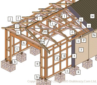
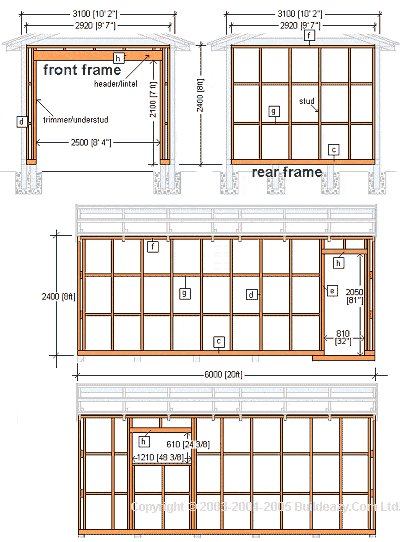
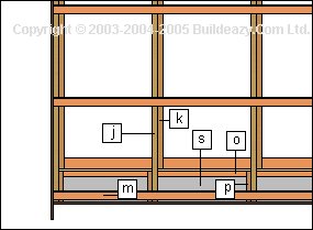
| [a] footing [b] post/pile [c] bottom plate / wall plate/sole plate [d] stud [e] trimmer / under stud [f] top plate [g] dwang / nogging / blocking [h] header/lintel | [i] ridge board [j] rafter [k] ceiling joist [l] cleat [m] purlin [o] ribbon plate [p] sprocket [s] soffit / eaves lining | [t] strap bracing [u] ribbon, wire or similar roof underlay support [v] roof underlay [w] roofing iron [x] wall cladding underlay [y] wall cladding / siding [ba] barge board / rake board [fa] fascia board |
Flat plan
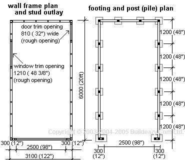
Wall frame plan and stud outlay
- This plan shows the placement of the studs from a bird’s-eye-view. In this particular plan, the studs are spaced at 600 [2ft] crs or o.c. (which means “at centers” or “on center”). This means the studs are spaced apart 600 (2ft) from the center of one stud to the center of the next stud.Studs spaced at 600 [2ft] crs/o.c. are also placed appropriately to accommodate standard width 1200 [4ft] cladding or lining, either exterior or interior.
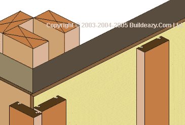
Footing and post (pile) plan
- This plan shows the placement of the posts and where the footing holes should be dug, from a bird’s-eye-view. The holes should be 300 [1ft] square and at least 450 [18″] deep.
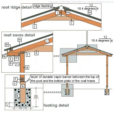
- In colder areas the footings should go below the frost line.There should be a thickness of concrete at least 100 [4″] between the underside of the post and the bottom of the hole. The holes should be spaced at max 1200 [4ft] crs/o.c. (at centers/on center).NOTE: The posts should be a minimum of 150 [6″] above ground level, with a layer of durable vapor barrier between the top of the post and the bottom plate of the wall frame (sole plate/bottom plate/wall plate).
The wall frames
The roof
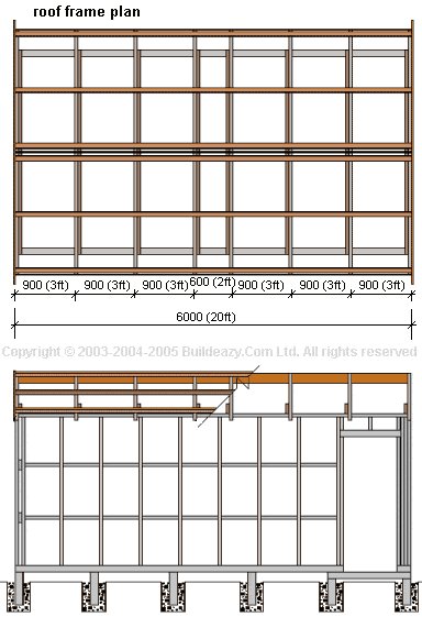
- Space the rafters at 900 [3ft] crs/o.c. beginning from the two ends of the garage frame (front and back) and work inwards towards the center.
- The spacing between the middle rafters will be less.
Detail
| [a] | Footing 300 [1ft] square x 450 [18″] deep | [m] | Purlin 75 x 50 [2×3] |
| [b] | Post/pile can be 100×100 [4×4] or 125×125 [5×5]. Treated for in-ground applications. | [o] | Ribbon plate 50×50 [2×2] fixed against wall frame to take sprockets |
| [c] | Bottom plate / wall plate / sole plate | [p] | Sprocket 75×40 [1-1/2×3]. Member from wall to fascia to support soffit |
| [d] | Stud. 100×50 [2×4] upright wall frame member | [s] | Soffit. 4.5 [1/4″] thick under eave cover |
| [i] | Ridge board 150×25 [1×6] | [w] | Roofing iron |
| [j] | Rafter 100×50 [2×4] | [y] | Exterior wall cladding |
| [k] | Ceiling joist 200×50 [2×8] spans the width of the garage and is fixed to the rafters | [fa] | Fascia board 150×25 [1×6] |
| [l] | Cleat 100×50 [2×4] goes directly under ridge board and fixed to rafters |
The eaves

| [f] | Frame top plate 100×50 [2×4] | [p] | Sprocket 75×40 [1-1/2×3]. Member from wall to fascia to support soffit |
| [j] | Rafter 100×50 [2×4] | [s] | Soffit 4.5 [1/4″] thick under eave cover |
| [k] | Ceiling joist 200×50 [2×8] spans the width of the garage and is fixed to the rafters | [ba] | Barge board 150×25 [1×6] |
| [m] | Purlin 75×50 [2×3] | [fa] | Fascia board 150×25 [1×6] |
| [o] | Ribbon plate 50×50 [2×2] fixed against wall frame to take sprockets |
Eaves section
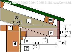
- The ribbon plate [o] is fixed horizontally to the side walls 96 [3-3/4″] down from the top plate [f]. This is called the “drop height”.
- The sprocket [p] or “soffit board” is a horizontal member fixed to the end of the rafter and to the ribbon plate. The eaves lining[s] is attached to the sprockets and usually also slotted into a groove in the fascia board [fa].
Cladding at the end of the eaves
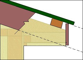
- The cladding at the end of the eaves follows the rake of the roof and is cut horizontally flush with the bottom of the fascia board.
- The eaves lining or soffit, can then butt up to the cladding.
The exterior cladding

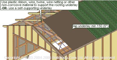
Cladding underlay
- A cladding underlay should envelop the exterior walls prior to the cladding being fixed.The cladding, 12.5 (1/2″) plywood can then be fixed to the studs. All joins should be on a stud and with a gap of 3mm (1/8″) between sheets.
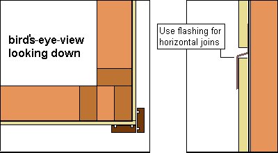
The battens
- Timber battens 75×25 (1×3) to go over each join. The battens should have a groove each side of the join to stop water being drawn up by capillary action.
- Extra battens can also be fixed to intermediate studs. This is for decorative purposes only.
The roof cladding
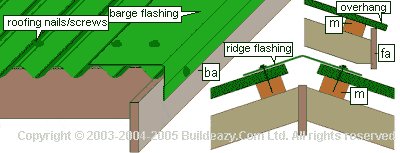
- Roof nailing: Fix the roofing iron to the purlins (m) with appropriate roofing nails/screws. Fix to the top and bottom purlins at every second corrugation and fix to the intermediate purlins at every 3rd or 4th corrugation. Fix through the high side of the corrugation.
- Roof overhang: Overhang the roofing approx 65 (2 1/2″) past the fascia board (fa) or 50 (2″) past the back of the gutter.
- Ridge flashing: Usually standard about 130 (5″) each side of the apex but can vary and any size can be made to order. Have the ridge flashing in mind when positioning the top purlin. Fix to the purlin at every second corrugation.
- Barge flashing: The barge flashing goes under the ridge flashing at the top. Fix to each purlin (through two corrugations) and also to the barge board (ba)
The angle cuts
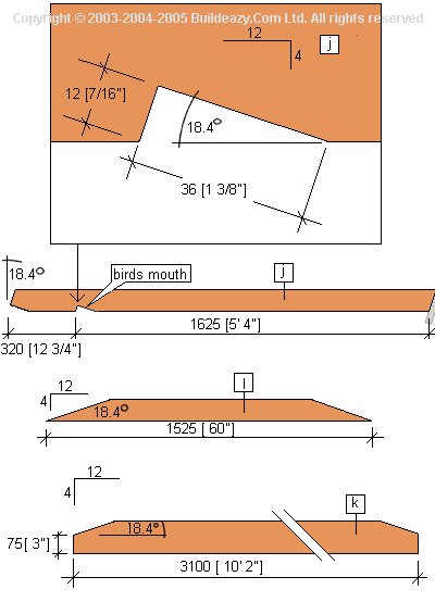
The roof frame members
- These are the only frame members that require angle cuts.
- Cut the roof frame members to the dimensions shown.
- [j] rafter
- 100×50 (2×4) stock. Cut to dimensions shown. 16 lengths required.
- [k] ceiling joist
- 150×50 (2×6) stock. Cut to dimensions shown. 8 lengths required.
- [l] cleat
- 100×50 (2×4) stock. Cut to dimensions shown. 8 lengths required.
- NOTE: Cut one set first (2 rafters, 1 cleat and 1 ceiling joist) and try for size and fit, before pre-cutting the entire roof frame.
Bracing and Fastening
Bracing
- WALLS: The plywood cladding (in most cases) will be more than enough wall bracing on its own right, provided each sheet joins on a stud and ample nails are placed around the perimeter of the plywood sheets, i.e. flathead nails 150 (6″) apart. The intermediate nailing can be spaced every 300 (1ft). Only the sheets that make up the bracing elements will need to be nailed in this fashion.
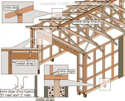
- ROOF: Use diagonally opposed metal galvanized strap, 25×1 (1/16×1″) with tensioners on each plane, as shown in drawing for the roof bracing. Each end of the strap should be folded over and fixed to rafter top and sides.
Fastening against uplift
- The garage needs to be fastened against uplift, from the footings to the roof. The posts [b] can be fastened to the bottom plate [c] with wire dogs, metal strap, galvanized plate bolted to post and bottom plate, or any other approved fastener. The bottom plate [c] can be fastened to the stud [d] with wire dogs or metal strap and likewise the stud [d] to the top plate [f]. Only studs over or near the posts need to be fastened this way.
- The rafters [j] can be fastened to the top plate [f] with wire dogs (z nails), two per rafter. The header [h] also can be fastened to the trimmer [e] and top plate [f] with metal strap.
Materials list
Amounts have been added on to allow for wastage. Stock sizes are nominal sizes(see glossary)
Excludes flashings and hardware such as nails and other fixing or fastening components.
| ID | Size (nominal) | Comments | Quantity | |
| Foundation | Concrete | For footing holes | .6 cubic metre (3/4 cubic yard) | |
| Sub-floor | Posts/Piles | 100×100 (4×4) OR 125×125 (5×5) | Natural decay-resistant lumber or treated for in-ground applications. | 9m (30ft) |
| Framing Wall | Bottom Plate | 100×100 (4×4) | Natural decay-resistant lumber or treated for in-ground applications. | 19m (62ft) |
| Framing Wall/Roof | Top Plate; Studs; Trimmer Studs; Cripple Studs; Header; Nogging; Rafters; Cleats | 100×50 (2×4) | 200m (656ft) | |
| Framing Roof | Ridge Board | 150×25 (1×6) | 6m(20ft) | |
| Framing Wall | Header | 200×50 (2×8) | 5.4m (18ft) | |
| Framing Ceiling | Ceiling Joists | 150×50 (2×6) | 26m (85ft) | |
| Framing Roof | Purlins | 75×50 (2×3) | 38m (125ft) | |
| Framing Eaves | Ribbon Plate | 50×50 (2×2) | 12m (20ft) | |
| Framing Eaves | Sprockets | 75×40 (1-1/2×3) | 5m (16ft) | |
| Roof Trim Garage Door Trim | Fascia; Barge Board; Door Trim | 150×25 (1×6) | 28m (92ft) | |
| Eaves Lining | Fibre-cement Sheet (or other soffit board) | 4.5 (3/16″) thick | 3.6sq m (40sq ft) | |
| Roof Underlay | Roof Underlay | 21sq m (226sq ft) | ||
| Siding Underlay | Siding/Cladding Underlay | 40sq m (430sq ft) | ||
| Roofing Iron | Corrugated | 21sq m (226sq ft) | ||
| Siding/Cladding | Plywood | 2400x1200x12 (4ftx8ftx1/2″) | 14 sheets | |
| Roof Bracing | Strap Brace | 25×1 (1/16×1″) | Tensioners on each plane (4 of) | 25m (80ft) |
| Exterior Battens | Vertical Joins; Corners. | 75×25 (1×3) | 90m (300ft) | |
| Exterior Beading | Under Eaves Beading | 25×25 (1×1) | 12m (40ft) |
Cutting list
| Item | Size (nominal) | Length | Number |
| Posts/piles | 100×100 (4×4) OR125×125 (5×5) | 500 (20″) | 16 |
| Bottom plate | 100×100 (4×4) | 6000 (20ft) | 2 |
| Bottom plate | 100×100 (4×4) | 2920 (9’7″) | 2 |
| Top plate | 100×50 (2×4) | 6000 (20ft) | 2 |
| Top plate | 100×50 (2×4) | 2920 (9’7″) | 2 |
| Studs | 100×50 (2×4) | 2265 (7’7″) | 34 |
| Trimmer studs for side door and window | 100×50 (2×4) | 1960 (77″) | 4 |
| Trimmer studs for garage door | 100×50 (2×4) | 2010 (6’8-1/2″) | 2 |
| Header garage door | 200×50 (2×8) | 2590 (8’7-1/2″) nail two together | 2 |
| Header side door | 100×50 (2×4) | 900 (35-1/2″) nail two together | 2 |
| Header window | 100×50 (2×4) | 1300 (51-7/8″) nail two together | 2 |
| Nogging, blocking, cripple studs, sill | 100×50 (2×4) | 37m (120ft) Random. Measure and cut on site. | |
| Purlins | 75×50 (2×3) | 6000 (20ft) | 6 |
| Ridge board | 150×25 (1×6) | 6000 (20ft) | 1 |
| Rafters | 100×50 (2×4) | 1625 (5’4″) 18.4 degrees or 4:12 angle-cut each end | 16 |
| Ceiling joists | 150×50 (2×6) | 3100 (10’2″) | 8 |
| Cleats | 100×50 (2×4) | 1525 (5ft) | 8 |
A guide to building the garage
Note 1: This is not step-by-step instructions on ‘how to build a garage’ but rather a guide explaining the order of things and helpful references. From time to time the Buildeazy website displays and updates help files in the form of step-by-step instructions relevant to Buildeazy plans.
Note 2: Regarding dimensions and sizes.
The dimensions are in both metric and standard (ft and ins). All metric references are in millimetres. In all references, the millimetre measurement precedes the standard measurement. The standard measurements are always denoted in parentheses( ). For example: “100×50 (2×4)”. Here, the 100×50 are millimetres, the (2×4) are inches.
Lumber sizes generally referred to are nominal sizes and not usually actual sizes. The nominal size is the rough-sawn size of a piece of lumber, before the lumber is planed or dressed. The nominal size is usually greater than the actual dimension. e.g. 100×50 (2 x 4) actually equals 90×45 (1 1/2″ x 3 1/2″). It is common practice to refer to a piece of 90×45 (1 1/2″ x 3 1/2″) lumber as 100×50 (2 x 4).
- Building Consent/Permit: Obtain all necessary Local Authority and Building Code approvals.
- Setting Out: Determine the position of the garage and “set-out” the BUILDING LINE using building PROFILES.
There is a detailed ‘Help File’ on erecting profiles at here - Materials: Have all materials stacked appropriately on site. All LUMBER should be stacked clear of the ground and on an even platform.
- Foundations: Mark FOOTINGS and dig holes. Pour concrete around and under POSTS/PILES. The POSTS/PILES can be either cut and placed at the correct height during the pouring of concrete, or placed over-height and cut to the correct height after the concrete has hardened. Take note of when inspections are required by your Local Authority. There is usually a FOOTING and position inspection required before any concrete can be poured.
- The Frame: Make the garage frame. First the wall frame and then the roof frame including PURLINS. There is a detailed ‘Help File’ on how to make WALL FRAMES at here
- Siding/Cladding: Fix the SIDING/CLADDING to the walls (over UNDERLAY)
- Barge; Fascia and Eaves: Nail the RIBBON PLATE to the outside top of the wall against the CLADDING at DROP HEIGHT (see Glossary). Fix the SPROCKETS to the RIBBON PLATE and RAFTERS, fix the BARGE BOARD to the PURLINS over the CLADDING at each GABBLE end, fix the FASCIA BOARD to the SPROCKET Ends and RAFTER Ends and then fix the EAVES LINING to the underside of the SPROCKETSand RIBBON PLATE.
- The Roof: Fix the roof (according to manufacturer’s instructions) over UNDERLAY followed by the barge flashing and the ridge flashing.
- Beading and Battens: Fix the BEADING to the underside of the EAVES and then fix the vertical BATTENS over every PLYWOOD join and at every corner. Other BATTENScan also be fixed intermediately for decorative purposes.
You now have a Garage Shell!