Contents
Introduction
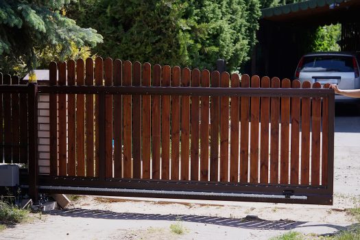
Time to replace the double hinged driveway gates with a single sliding gate. Why? For both practical reasons and convenience.
The existing gates were only a couple of years old and still worked fine (you can see the making of them here), but because of an uphill driveway, they were purpose-made with an ‘under-gate extension’ device that had to be raised every time the gates were used. Also, when the gates were open they took up too much room, which made it difficult to park extra vehicles off the driveway.
We thought it would be easier and more practical to have a sliding gate in this particular situation.
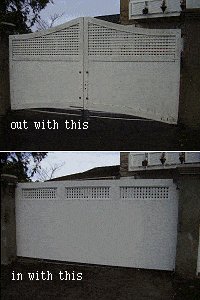
So out with the old and in with the new.
I wanted a sliding gate made solely out of lumber.
I had never made or installed a sliding gate before, so I popped in to the local gate makers to get an idea or two.
One of the first things I found out was that most substantial sliding gates required a metal frame to prevent warping. But I didn’t want a metal frame. I wanted a gate made solely out of wood.
Because I couldn’t find a local gate company that actually made wooden sliding gates and I was unable to get any structural ideas, it was a matter of having to design my own. Page 2.
Will the wooden gate warp?
We will find out in time and keep you posted in the update page 8.
What if the gate does warp?
Ahh, there is a back-up plan in mind. I may have to admit defeat (at least with this particular design) and run a piece of metal angle completely around one side of the gate to stiffen it up. However, I don’t think it will come to that.
Gate Components
Apart from the gate, I needed a track, wheels, guide rollers and some sort of latch that would hold the gate closed.
I had no trouble obtaining most of the hardware from any number of fence and gate companies, apart from a suitable latch. I decided to design my own. Page 2.
The gate plan, wheels and the latch design
The gate design
Making a sliding gate solely out of wood was going to take a little bit of thought as my inquiries told me that most substantial sliding gates required a metal frame to prevent warping.
I was pretty confident that I could make a gate out of wood that would not warp but it would have to be a specific design.
I decided on a design not unlike an interior house wall, comprising of a ‘wall frame’ with lining (covering) on both sides of it. (Scroll down to see the frame plan.)
I also wanted some small windows with lattice in the gate, so it would not look too much like a solid wall.
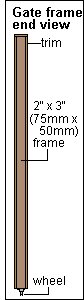
I made a wall-type frame out of 2″x3″ (75mm x 50mm) lumber and covered both sides with 1/2″ (12mm) plywood.
The plywood (nailed and glued adequately) would act as a brace. I also incorporated additional diagonal bracing into the frame.
I figured that having both sides of the frame covered and braced with plywood would help to prevent warping, because any movement in the wood (such as shrinkage/expansion) should be equal on both sides, thus cancelling any forces that might cause the gate to warp. Anyway, that was my theory.
I also ensured that the frame was well fixed with nails and metal strap, the plywood was well glued and nailed, and that there was a good covering of paint.
Gate frame plan
Approximately 12ft (3600mm) wide x 6ft (1800mm) high
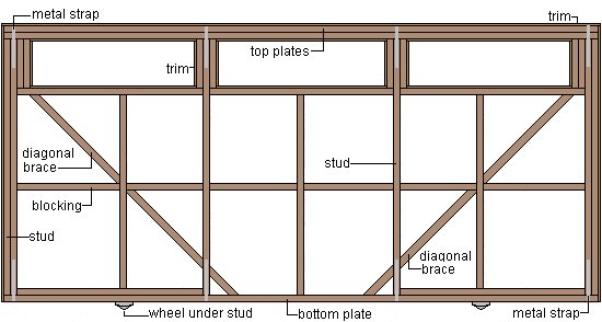
The gate frame was made out of 2″x3″ (75mm x 50mm) lumber.
2″x4″ (100mm x 50mm) lumber could also be used and would be just as good – if not better – as the wider the lumber, the more rigid the gate will be. However, the wider the lumber, the heavier the gate will be.
The wheels
The wheels were easily obtainable from any number of fence and gate companies. The wheels that I used had a loading of 440lb (200kg) each, which meant that the two of them together could support a gate that weighed up to 880lb (400kg).
My gate came well under that (I think).
The wheels had a ‘U’ groove, a diameter of 3″ (75mm) and were 1″ (25mm) wide.
Latch design
Because I couldn’t find a suitable latch to suit my requirements, I designed my own, took the design to an engineer and had it made. The latch worked very well and was exceptionally strong.
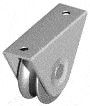
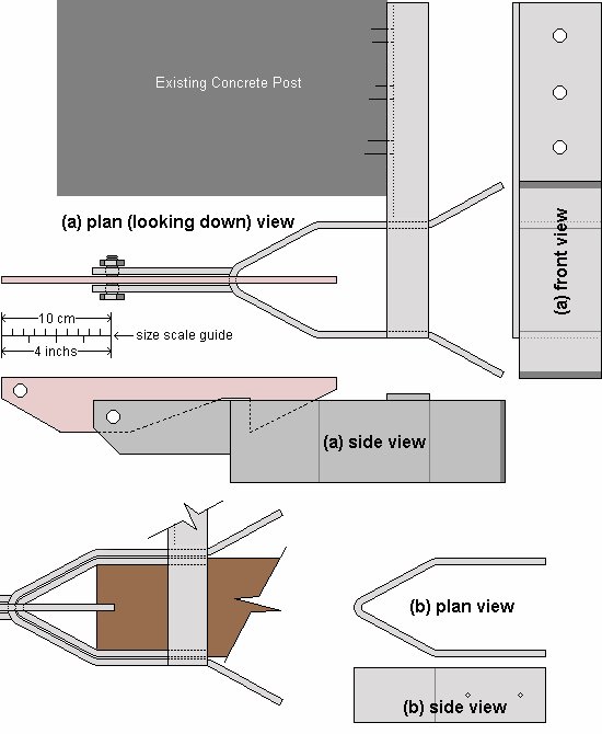
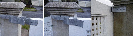
It basically consisted of one piece (b) that was fixed to the top of the gate and another piece (a) that was bolted to the top of the gate post.
Piece (b) slid into piece (a) and clicked shut.![]()
Below is the design I took to the engineers.
Preparing the grade for the track
I wanted a continuous straight line for the track. Maybe I’m a bit fussy, but if the track has a horizontal curve then the gate will still slide alright but it may not align vertically with the posts in both open and closed position. Anyway, I figured that a straight track would give an even pull and/or push when working the gate. (Don’t confuse straight with level. I wanted the track straight but running slightly downhill away from the drive.)
I wanted the track running downhill a little towards the open position so that the gate would stay open (without the need of catches) and not accidentally roll into passing vehicles.
I made it so that track had a fall of 3/4″ (20mm) over the length of the gate.
The existing concrete surface was curved so I decided to cut a straight trench in the concrete, wide enough to take the gate track.
I also needed something solid on the side of the driveway to fix the track to.
For this, I used a post set horizontally in concrete.
The grade plan

Cutting a trench into the concrete
Because the existing concrete surface was curved, I decided to cut a straight trench in the concrete wide enough to take the gate track.
I determined the position of the trench line.
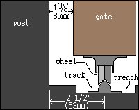
The gate was to be 3 1/2″ (90mm) thick and I wanted the gate 1 3/8″ (35mm) in from the posts, therefore the center of the track would be 2 1/2″ (63mm) in from the posts.
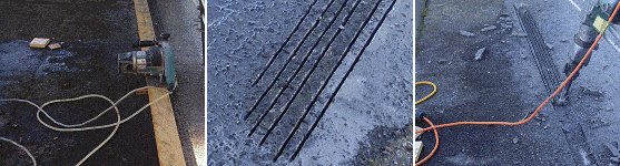
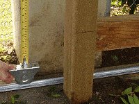
I used a straight piece of wood as a platform for the cutting saw to run on. I determined the height with a string line and level.
I then set the blade on the cutting saw to the required depth and made multiple cuts in the concrete.
I cleaned out the trench with a chisel (see picture above).
Determining the line and digging a trench in the ground

I ran a string line along the middle of the trench (in the concrete) and down to where the track would finish. This enabled me to determine where to dig the trench in the ground and where to place the horizontal post (track support).
I then dug the trench to a depth and width that would accommodate the horizontal post and about 4″ (100mm) of concrete below and around it.
Setting a post horizontal for the track support

I then mixed a batch of concrete and placed it in the newly dug trench.
I placed the 4″x4″ (100mm x 100mm) post horizontally on the freshly poured concrete and adjusted it (using the string line as a guide) until it was the right height.
I now had a continuous straight surface to fix the track to.
Putting in the fence posts
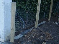
I also decided to build a little 4ft (1200mm) high fence along the side of the gate when it was in an ‘open position’.
This would protect things from getting in the way of the gate and also keep grandkids out of harm’s way.
At this stage, I just put in the fence posts so I could still get in to fasten the track.
Installing the track and measuring the gate height
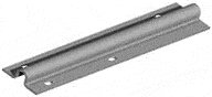
I used a ‘U’ (half-round) profile track that was pre-drilled and galvanized.
The track was easily obtainable from any number of fence and gate companies, and came in 20ft (6m) lengths.
By now, I had a continuous straight surface to fix the track to so it was really just a matter or laying the track in place and securing it to the surface using the appropriate fasteners.
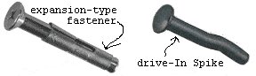
To fasten the track to the concrete I used two types of fasteners (just to try them out):
1) A Concrete expansion-type fastener.
2) Drive-In Spike Concrete Fasteners.
For both types, I had to first drill a hole into the concrete the same thickness of the fasteners.

To fasten the track to the wood I used wood screws and galvanized nails.
Determining the gate height
Just about time to start making the gate.
I already had the gate plan in mind (I had to know the thickness of the gate in order to fix the track in the right place), and once the track was in place I was then able to determine the exact height that I needed to make the gate. I did this by measuring from the top of a wheel (which I held on the track) to wherever I wanted the top of the gate to finish.
Making the gate
I knew the sliding gate would have to be strong and built well to minimize any warping.
I decided on a design like interior house wall, comprising of a ‘wall frame’ with lining (covering) on both sides of it. You can see the frame plan (Page 2).
Having both sides of the frame covered and braced with plywood should help to prevent warping, as any movement in the wood (such as shrinkage/expansion) should be equal on both sides, therefore cancelling any forces that might cause the gate to warp.
I made the frame out of 2″x3″ (75mm x 50mm) lumber and covered both sides with 1/2″ (12mm) plywood.
The plywood (nailed and glued adequately) would act as a brace. I also incorporated additional diagonal bracing into the frame.
I also ensured that the frame was well fixed with nails and metal strap, the plywood was well glued and nailed, and that there was a good covering of paint.
Below is a sequence of photos showing the building process, followed by an explanation of each photo.
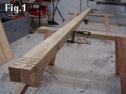
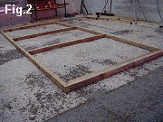
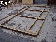

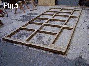

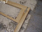
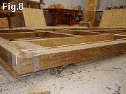
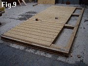
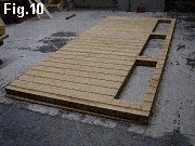
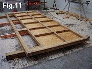
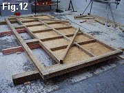
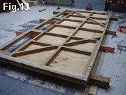
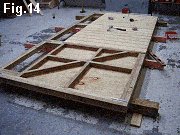
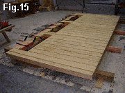
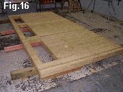
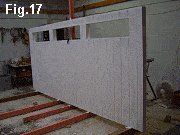
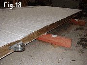
Fig.1 The top and bottom plates placed together so that the stud positions can be marked.
Fig.2 The plates spread apart on the ground and the studs positioned on the marks.
Fig.3 The window holes made (for the lattice).
Fig.4 The intermediate studs positioned and fixed.
Fig.5 A row of blocking fixed in place.
Fig.6 Metal strapping around the plates fixed to the tops and bottoms of the studs.
Fig.7 A closer look at the metal strapping.
Fig.8 The plates made straight using a string line and packers.
Fig.9 1/2″ (12mm) treated grooved plywood glued and nailed in place.
Fig.10 More 1/2″ (12mm) treated grooved plywood glued and nailed in place.
Fig.11 The frame turned over.
Fig.12 Diagonal bracing lengths laid in place to be marked for cutting.
Fig.13 Diagonal bracing pieces glued and nailed in place.
Fig.14 More 1/2″ (12mm) treated grooved plywood glued and nailed in place.
Fig.15 The trim glued, nailed and clamped in place.
Fig.16 Clamps taken off, ready for painting.
Fig.17 The painting commences.
Fig.18 The wheels are fixed to the bottom of the sliding gate.
Installing the gate and making the end stop
Putting the gate in was no problem, simply a matter of standing it up with the wheels over the track.
Stopping the gate

I wanted something that would be able to stop the gate without too much of a jolt should somebody push open the gate with an almighty force.
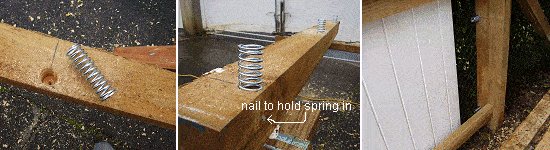
I thought that I would put a post at the end of the track, with three springs to cushion the blow of a swiftly opened gate – after all, it was a relatively heavy gate.
I acquired three springs that I thought would do the trick and then drilled three holes in the post the same diameter as the springs.
I drilled the holes 2″ (50mm) deep in a 4″x4″ (100mm x 100mm) post.
To hold the springs in, I hammered a nail through the side of the post into the bottom of each spring.
Fitting the Latch and guide rollers
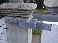
The guide rollers
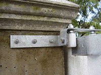
Because of the width of the gate, I couldn’t find a suitable roller guide so I had to make my own.
However, I could get the rollers from a gate manufacturer and I obtained a couple of galvanized ‘L’ brackets from the hardware store. I then had the components.
I bolted and welded the two ‘L’ brackets together, drilled a couple of holes to take the rollers, positioned the unit over the gate and bolted it to the post.
The latch
The latch was a different kettle of fish. I couldn’t find anything that suited so I had to design my own and have an engineer make it for me.
I wanted something that would work easily, lock the gate to prevent lifting and be very strong.
You can see the design (Page 2) and some photos below.
That’s it! Done! Finished! Updates will be posted on the next page.
Updates
Because the sliding gate is made solely out of wood, we want to see how it stands the test of time. Periodically, an update report will be posted on this page.
10 weeks on
10 weeks on – the gate has been getting plenty of use and I am extremely pleased with it. It is well balanced, slides with ease and there is not a hint of any movement in the wood.
Having said that it is still early days and although the gate has had plenty of use, it has not yet had to put up with extreme temperatures but things are looking pretty good at this stage.
I will give another report in a couple of months and we’ll see then how it’s going.
Over a year down the track
The gate has been up and running for over a year and deserves a pass.
This will be the last update report, as the gate has been through all seasons, endured storms, all weather conditions and temperatures, and probably had above average usage as there have been five vehicles housed behind the gate coming and going all times.
The gate is every bit as good as the day it was put up.
I guess it could be put down to the design and a good covering of sealant/paint to keep the water out.


Where are the plans?
Very well thought-out and designed gate. Mongo Impressed!
I just got a quote for $5100 for a metal gate of similar size. That’s a bit too steep, so I too am going to build my own gate using 26gage, 2’X 3″ galvanized downspout (I’m a retired sheet metal contractor)for the frame, then T-111 plywood to cover. I’ll install some wood structure inside to attach the cover.
Since this proposed gate is on an alley, it doesn’t need to be too attractive. Just sturdy. “Prison wall” is the look I’m going for. As I expect to have no help with the construction and installation, the trick will be to build it in place on the track.
Thanks, Les, for the inspiration! You’re right about protecting the gate, inside and out from the elements. Los Angeles is “mild-weather climate,” but wind and rain (no snow or hurricanes) are concerns.
I hope to use the money I’ll save on a nice scuba vacation in Thailand or the Philippines.
I’ve spent a little time online searching for the appropriate hardware; wheels. track, and rollers can all be found on Amazon.com if not locally sourced. I haven’t priced much of anything, but hope to keep the cost (aside from my labor) to well under $1000.
Just curious, cost of total materials involved, Thanks in Advance
I love this idea of the sliding gate! Where can I get the plans for the gate and maybe a materials list? I think I can get everything else from the article.