Contents
Introduction – Plans – Lumber
Introduction
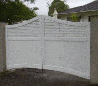
A fair amount of thought had to go into the design of these gates.
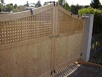
The driveway had an uphill slope, therefore the bottom of the gates had to be about 250mm (10″) above the ground in closed position to allow the gates to open over the sloping drive.
There are ways that gates can be hinged off vertical to enable the gates to lift over raised ground such as can be seen here, but with the ‘hinge offset’ method, the gates look a bit askew when opened and gravity can cause the gates to swing shut a bit faster than intended.
With that knowledge in hand, we decided to go with gates which would open on a level plane, meaning that the gates would have to be fixed to the posts high enough so they could open without hitting the up-sloping driveway.
This meant that the gates had to be about 250mm (10″) off the ground in closed position.
To achieve this, we’d have to devise some type of contraption to stop kids and dogs from scrambling underneath, while still allowing the gates to easily open. And that is exactly what we did.
The device, which we called ‘the under-gate movable extension’ for lack of a better term, can be seen on page eight.
Scroll down for the plans and lumber description.
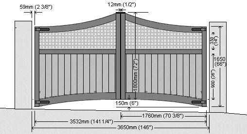
The Plans
Lumber used
The lumber used in this project was dressed (surfaced, smooth) treated stock.
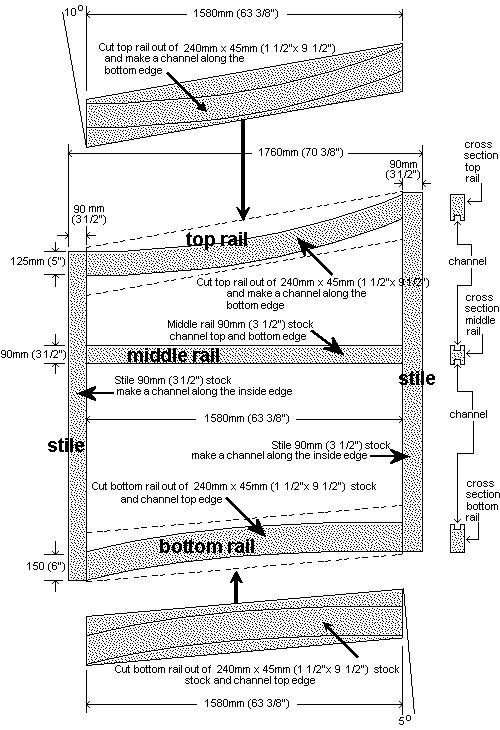
Stiles: (vertical frame members). The stiles were 90mm x 45mm (1 1/2″x 3 1/2″) stock.
Rails: (horizontal frame members). The middle rails were 90mm x 45mm (1 1/2″x 3 1/2″ stock. Both the top and bottom rails were cut out of 240mm x 45mm (1 1/2″x 9 1/2″) stock.
Bottom panels: 140mm x 20mm (3/4″x 5 1/2″) tongue and groove stock.
Top panels: Lattice to suit.
Marking, cutting and trenching the members
Note: This example explains how these particular gates were made to a specific size for a specific job.
Chances are, your gates will need be a different width and probably open over a different ground contour. Therefore, use this example as a guide only and make any necessary adjustments.
The plans and dimensions for these gates can be seen Page 1.
The members marked, cut and trenched (grooved)
Marking the curved top and bottom rails
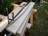
- The gate top and bottom rails were cut out of 240mm x 45mm (1 1/2″ x 9 1/2″) stock. Refer to the plans (Page 1) for dimensions and drawings showing the curved shape.
- A strip of thin wood was bent in a curve and used to mark the cutting line.
Cutting the curved top and bottom rails
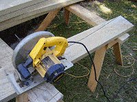
- Because the curve cut was gradual (not too sharp), it could be cut using a circular saw.
Note: The circular saw blade was set to a depth just slightly more than the thickness of the lumber and the cutting blade had reasonably big teeth.
Marking for the second cut
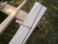
- A scriber (just a stick with a guiding nail in it) was used to mark a line parallel to the first cut.
- The second cut was also made using a circular saw.
Making the trench (grove)
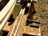
- A 20mm (3/4) deep trench was made with a router in the bottom edge of the top rail, the top edge of the bottom rail, both edges of the middle rail and one edge of each vertical stile.
- The width of the trenches was slightly wider than the thickness of the tongue and grove and lattice respectively.
Constructing the bottom T&G panel
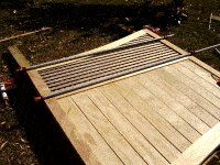
Laying the members in place
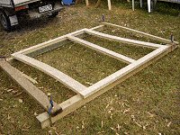
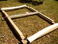
- Once cut and trenched, the gate members were laid out in place to ensure that all pieces fitted and the dimensions were as shown in the plans (Page 1).
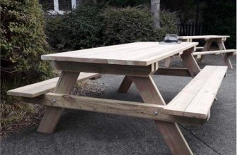
- The members were laid out on top of a makeshift frame simply because there was not a large working table or platform available.
Securing the middle rail
- The three rails were removed.
- Glue was applied to both ends of the middle rail and then the middle rail was re-placed back into position.
- The two side stiles were firmly clamped against the middle rail.
- The middle rail was then nailed to the side stiles by way of angling (toe-nailing) nails through the edges of the middle rail into the style, four altogether per gate: one at each corner.
Inserting the tongue and grove boards
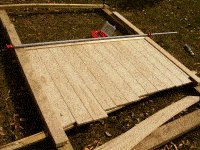
- The T&G (tongue and groove) boards were applied with dabs of glue along the edges and then inserted into the trenches (grooves).
- All the T&G boards except the first and last were cut over length.
- A packer was placed under the ends of the boards to stop them from sagging.
- The two stiles were constantly checked to ensure that they remained parallel.
Marking the bottom cut line
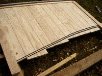
- The bottom rail was placed on top of the T&G boards in position so the curve line could be marked on the T&G boards.
- Another line was marked 15mm (5/8″) down from and parallel to the first line.
- The portion between the two lines was the amount that was to go into the trench (grove) in the bottom rail.
Cutting the T&G boards
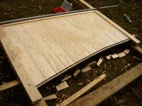
- The bottoms of the T&G boards were then cut along the bottom line.
Completing the lower panel
- Glue was applied to the bottom ends of the T&G boards and to the ends of the bottom rail.

- The bottom rail was fitted in place in between the two stiles and with the channel over the bottom ends of the T&G boards.
- The two side stiles were then firmly clamped against the bottom rail.
- The bottom rail was then nailed to the side stiles by way of angling (toe-nailing) nails through the bottom edge of the bottom rail into the style, two altogether per gate: one at each end.
Constructing the top lattice panel
Inserting the lattice

- The lattice was cut the correct width but kept over length.
- Glue was applied to the edges of the lattice and dabs of glue were applied to the channels.
- The lattice was inserted into the channels.
- The lattice was marked and cut in exactly the same way as the bottom T&G boards were marked and cut as explained in the previous page (Page 3).
Adding the top rail
- After applying glue, the top rail was fitted in place in between the two stiles and with the channel over the top of the lattice.
- The two side stiles were then firmly clamped against the top rail.
- The top rail was then nailed to the side stiles by way of angling (toe-nailing) nails through the top edge of the top rail into the stile, two altogether per gate: one at each end.
Adding additional strengthening
Adding galvanized metal plate
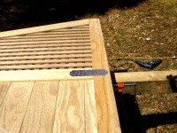
- Outside gates can take a fair bit of punishment so you can never make them too strong.
- A few galvanized metal plates/straps over the joins won’t spoil the look one bit if the gates are to be painted.
- Galvanized metal plates were fixed over each middle rail and stile meeting, eight altogether: four on each gate.
Adding galvanized metal strap

- Galvanized metal straps were fixed over the ends and edges of each top/bottom rail and stile where they met. There were eight altogether: four on each gate.
Gate installation
Aligning the gates
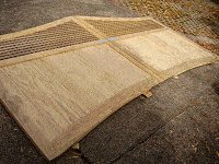
- The two gates were laid on the ground on top of packers and positioned in alignment with one another.
- There was a 12mm (1/2″) gap between the two gates.
Making the pair of gates steadfast
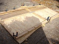
- Two pieces of 100×50 (4×2) were placed on top of the gates: one running along the top and one running along the bottom.
- Both pieces spanned the width of the two gates.
- The 100×50 (4×2) was securely clamped to the gates locking the pair in position with one another.
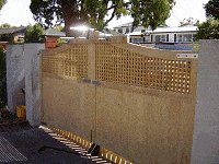
Lifting the gates into position
- The pair of gates, held together as one unit, were stood up and lifted into position between the gate posts.
- Packers were put under each end until the gates were the right height, and wedges were placed between the gates and posts to hold and centralize them between the posts.
Fixing the hinges
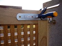
- Once the gates were positioned correctly, the hinges were clamped to the gate.
- This held the gates in position.
- The hinges were then fixed to the gate and the clamps were taken off.
Preparing for the gate fittings
- The two pieces of 100×50 (2×4) that held the gate in alignment were then taken off and replaced with one shorter piece clamped to the top of the two gates, to hold the gates rigid while the gate fittings were being fixed in place.
Gate hardware
Adding the hardware
Note: This page deals with the basic fittings which were required to open and shut the gates.
In does not take into consideration any of the fittings that were required for the ‘under-gate movable extension device’.
Information regarding the latter can be found on page 8.
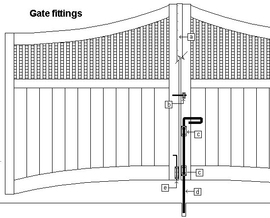
Below is a drawing of the gate fittings, followed by a description.
[a] A strip of wood about 10mm (3/8″) thick x 50mm (2″) wide was nailed on one side to one gate but covered both gates.
The strip ran from top to bottom of the gates. It had to be cut around any gate fittings that were in the way.
The purpose of the strip of wood was to stop the gates from warping.
[b] A standard gate latch.
[c] Galvanized L-shaped angle bracket with a 25mm (1″) hole in which the 20mm (3/4″) drop rod slides through.
[d] Drop rod made out of 20mm (3/4) diameter steel. The length of the rod is 900mm (3ft) high with a 200mm (8″) handle at right angles.
The drop rod was made at an engineering shop, since something so substantial could not be found at a building and hardware store. However it was a simple process to have it made and not very expensive.
[e] A standard drop bolt. This bolt is used to hold the gate in the open position.
Under-gate extension (part 1)
The under-gate movable extension
- This device was designed to fill in the gap at the bottom of the gates to stop the dog and kids from scrambling underneath.
- Sometimes a gap below a gate is created by necessity: in this case the gates had to be installed 250mm (10″) off the ground to allow them to open over an up-slopping driveway.
The working mechanism
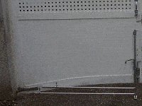
- The under-gate movable extension basically consists of a vertical pipe that can move up and down through the holes in two eye bolts, and two horizontal rods that are bolted to the lower portion of the vertical rod (per gate).
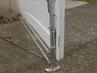
- There is an arched foot welded to the bottom of the vertical rod.
- When the gate opens, the arched foot slides on the driveway and when the gate opens over raised ground, the vertical rod rises accordingly, thus lifting the two horizontal rods.
Or…
- Alternatively he device can be lifted up via a handle fixed to the vertical rod and ‘clicked’ into the up position.
- The ‘clicked’ in up position makes for a smoother opening and less noise.
- You can see the plans and parts description on the page 9.
Under-gate extension (part 2)
Making the movable extension device
Note: This page deals only with the fittings required for the extension device.
In does not take into consideration any of the basic fittings which were required to open and shut the gates.
Information regarding the latter can be found on page 7.
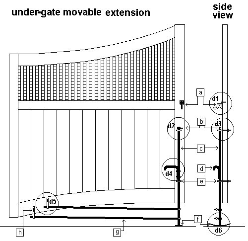
Below are drawings of the extension device followed by a description of all the parts. Scroll down.
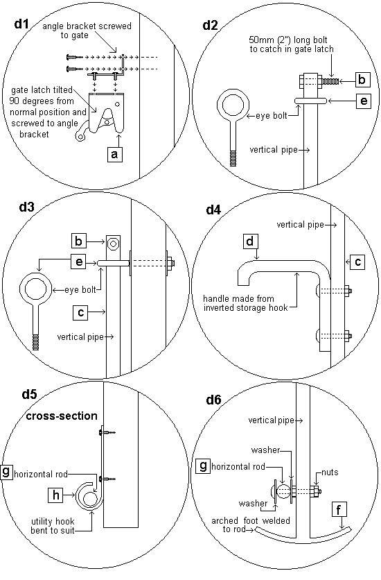
[a] A standard gate latch was turned to face down and screwed to an angle bracket. The angle bracket was then screwed to the gate.
[b] An 8mm (5/16″) bolt 50mm (2″) long. The bolt went through the top of the vertical pipe and stuck out.
When the vertical pipe was lifted up, the end shank of the bolt caught in the gate latch and stayed there until it was released.
[c] Galvanized vertical pipe 20mm (3/4″) outside diameter by 1000mm (40″) long.
[d] A handle was made using a storage hook bolted (upside down) to the vertical pipe.
[e] 8mm (5/16″) galvanized eye bolts with eye holes at least 25mm (1″) diameter so that the vertical pipe could easily move up and down in the holes.
[f] Galvanized arched foot that was welded to the vertical pipe. Approximately 6mm (1/4″) thick x 50mm (2″) wide x 125mm (5″) long and was able to slide along the concrete.
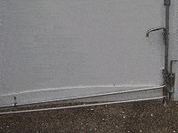
[g] Horizontal rod. Aluminum television aerial rod was used for this project. The rod size was 15mm (5/8″) thick. The top rods were 1350mm (54″) long and the bottom rods were 1500mm (5ft) long.
They were bolted to the vertical pipe (as shown in the drawings above) at one end and were able to run freely through hooks at the other end.
The rods had to be able to pivot at the vertical pipe end and move freely through the hooks at the other end.
[h] Utility hooks screwed to the bottom rails of the gates. The hooks were bent around so that the horizontal rods could not jump out. The hooks had a much bigger diameter than the horizontal rods so the rods could freely move.