Contents
Introduction

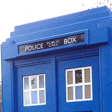
The London police box was a little shed type structure used mainly as a communications base for patrolling police officers prior to the age of mobile telecommunications.
Typically, the boxes were blue. They allowed patrolling officers to keep in touch with the station via a phone.
The boxes had a light on top that would flash to alert the patrolling officer that the phone was ringing.
The public could also use the phone in an emergency.
The Metropolitan Police introduced police boxes throughout London between 1928 and 1937.
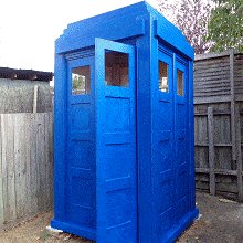
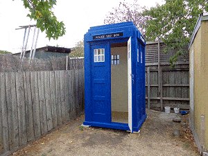
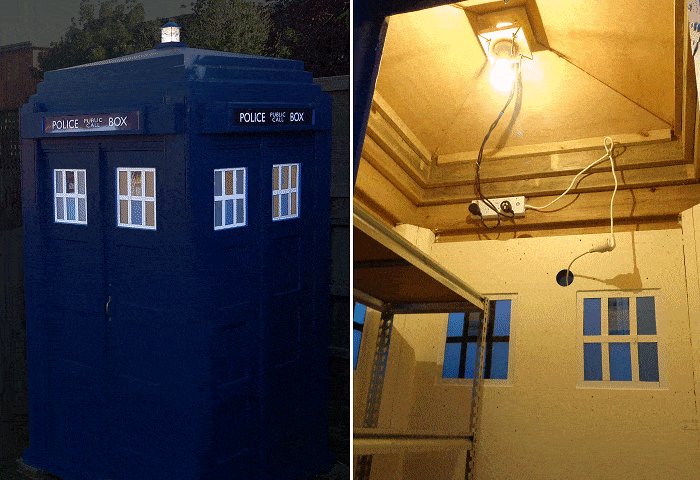
The Police Box was the inspiration for the well known TARDIS.
The TARDIS is a time machine featured in the very popular British science fiction television series “Doctor Who” that was first aired in 1963
The designs of the TARDIS props used in the television series have changed many times but none has really been an exact copy of the real police box.
Description
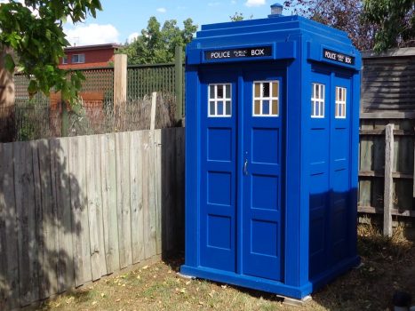
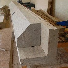
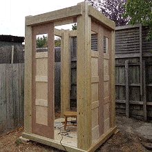
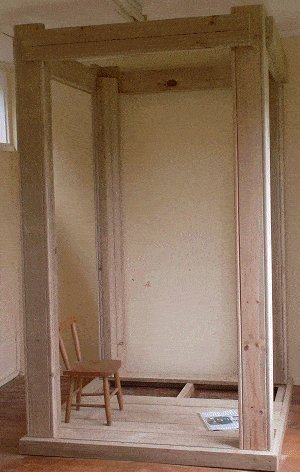
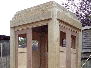
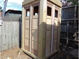
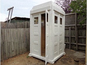
This police box is a very solid structure.
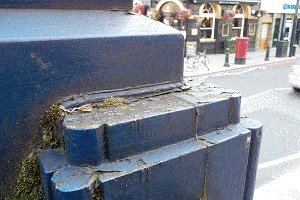
It is my take on the 1929 Mackenzie Trench design police watch box, very similar to (and the same size as) the Police Watch Box that sits outside Earls Court Railway Station in London.
The police box outside Earl’s Court tube station in London was built in 1997 and based on the 1929 Mackenzie Trench design.
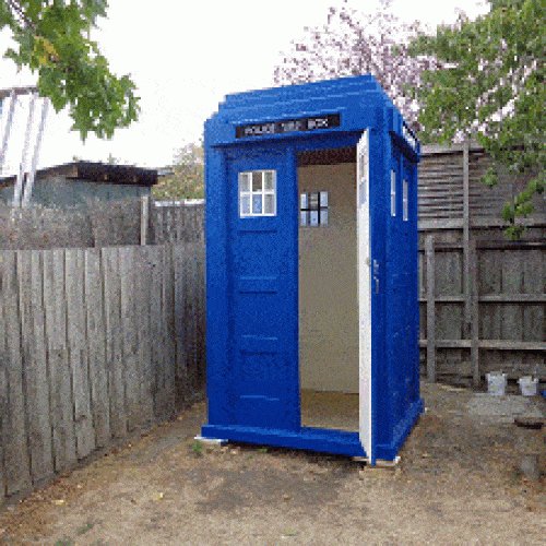
The police box here is not a prop.
It is a very solid structure suitable not only for show, but also for many practical uses. It is big and strong enough to be used as a garden shed to store garden tools etc., and it can be transformed into a cattery, a pool side changing shed, or any other type of quirky rendition that could be limited only by your imagination.
This is a full-size version very similar to the police box outside Earl’s Court tube station in London.
It is designed for outside use. The corner pillars alone could just about hold up a house.
It is made in sections that can be dismantled if it ever needs to be moved
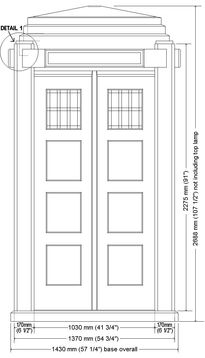
The footprint is 1430 mm (57¼”) square and it stands 2700 mm (9 ft) tall.
What’s ahead
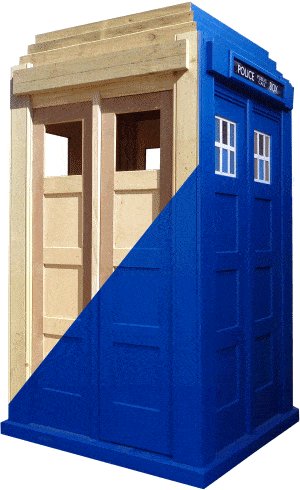
On the next couple of pages is a pictorial account showing in sequence the different building stages. The images can be clicked on to go straight to the relevant page in the instructions.
On the page after that are a few important explanations, followed by the plans, the materials list, and the step-by-step building instructions with plenty of pictures and drawings to help along the way.
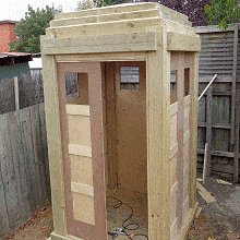
Photos of construction part 1
Photos of construction part 2
Explanations
An important note about the measurements used in this project
This project is written in both Metric (mm) and Imperial (inches).
Except for segments written separately for one system or the other, the metric measurements are given first followed by the standard measurements in brackets ( ) – for example: 100 mm x 50 mm (2″ x 4″).
The metric (mm) measurements given are not an exact match to their equivalent imperial (inch) counterparts.
Why
Because similar common stock sizes vary (in actual, true sizes) from country to country as does availability of certain stock sizes. This project has been written accordingly.
This project uses common stock sizes available in North America (imperial version) and common stock sizes available in Australasia (metric version).
They are not the same in real terms.
Other counties should be able to use one system or the other – the point is, use one system or the other. Do not combine the two because they are not an exact match.
Example
A basic piece of two-by-four (100 mm x 50 mm (2×4)) dimensional wood is actually 38 mm x 89 mm” (1½” x 3½) in real size in North America,
but…
In Australasia, the actual real size is more like 45 mm x 90 mm (1¾” x 3½”).
Also,
Australasia has a common wood size that is around 35 mm ( 1⅜”) thick. North America does not.
So there are some different wood sizes used in the metric version to that of the imperial version.
To reiterate: The stock (actual) sizes used in the metric version are different to those used in the imperial (inch) version
Australasian stock availability and actual sizes are different to those in North America.
A TARDIS built using the metric measurements will be a slightly different size to the same structure using the imperial (ft and in) measurements.
So use one system or the other but don’t mix and match, i.e., do not combine the two systems.
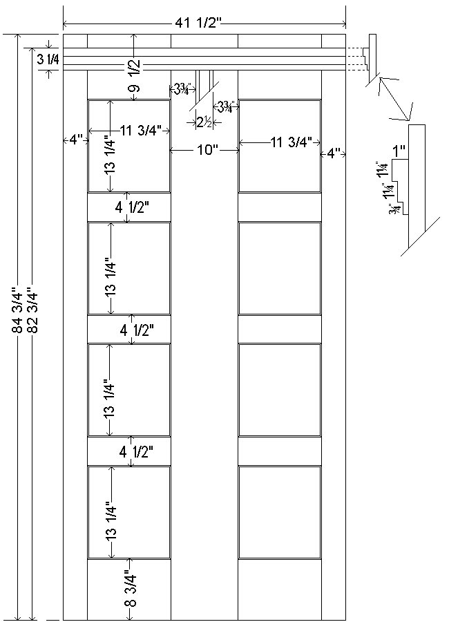
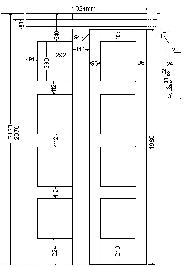
Plans – Front, floor and footprint
Plans – Front elevation and floor
Note: The metric (mm) measurements given are not an exact match to their equivalent imperial (inch) counterparts.
Refer to the ‘Explanations’ page for further explanation.
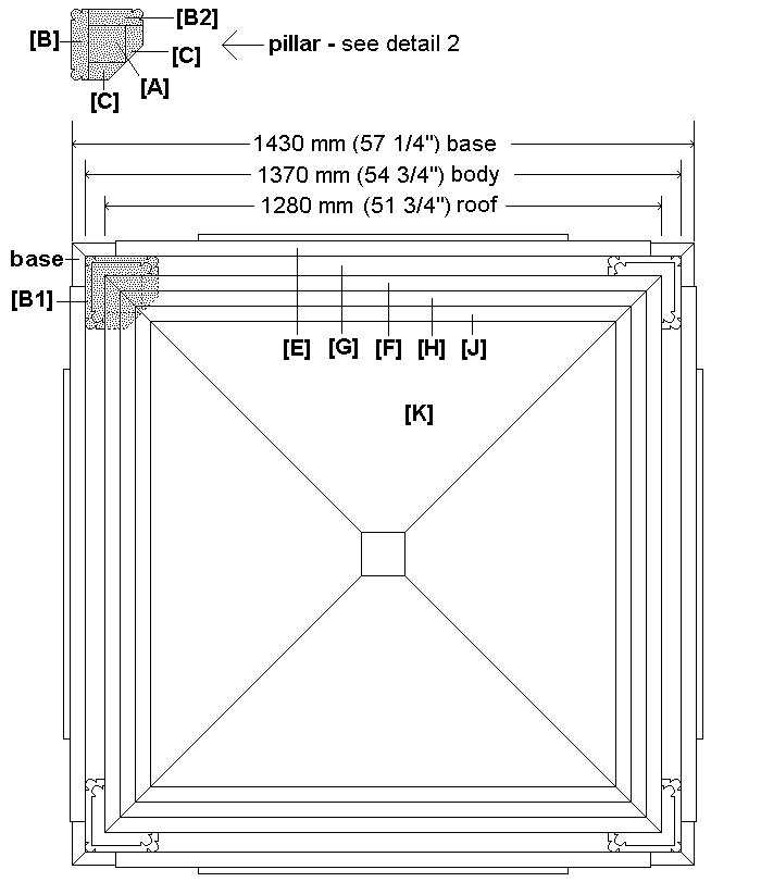
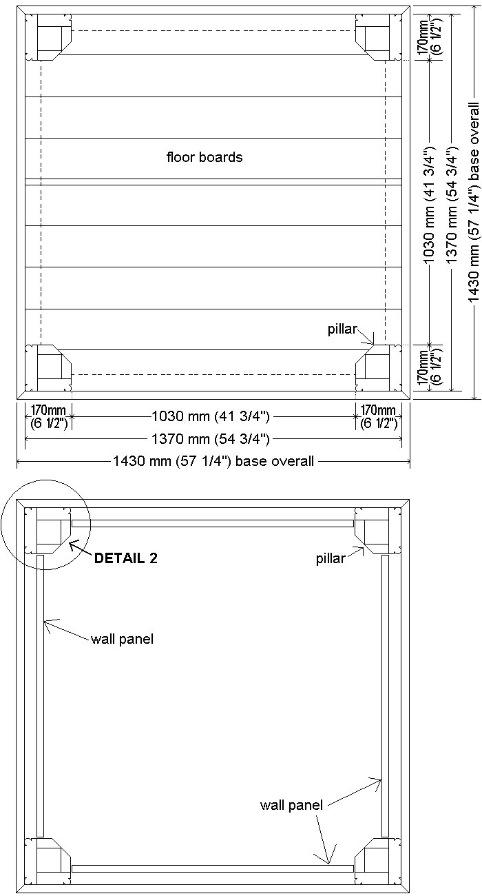
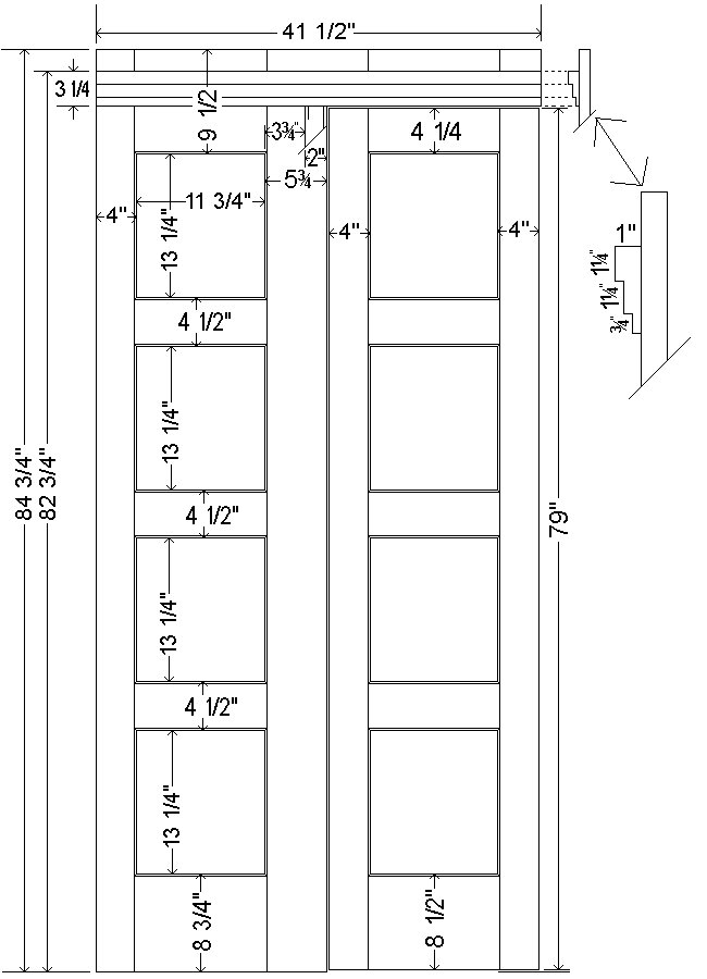
Plans – Footprint
Note: The metric (mm) measurements given are not an exact match to their equivalent imperial (inch) counterparts.
Refer to the ‘Explanations’ page for further explanation.
Plans – Base, floor, and wall layout
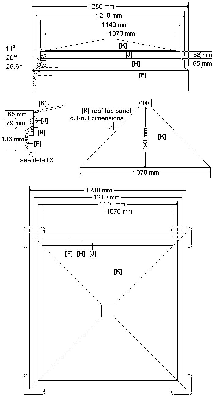
Plans – Top and roof (millimetres)
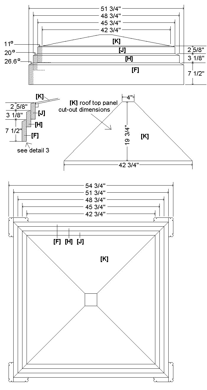
Plans – Top and roof (inches)
Plans – The sign


Note: The metric (mm) measurements given are not an exact match to their equivalent imperial (inch) counterparts.
Refer to the ‘Explanations’ page for further explanation.
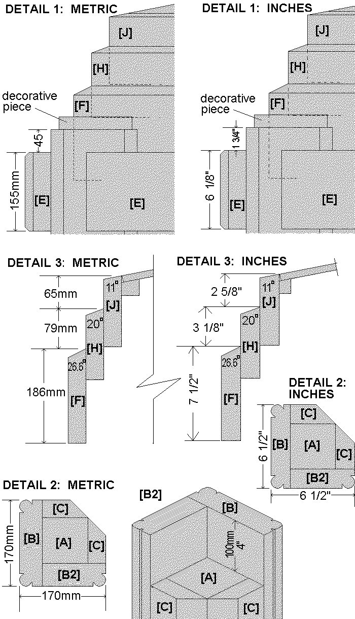
Plans – Details
Plans – Fixed walls – metric
Plans – Fixed wall – standard
Plans – Wall/door – metric
Plans – Wall/door – standard
Materials overall
Find out the standard lengths of wood available at your wood supplier and work out how much you will need to get the cuts listed below. Your supplier could even do that for you. Common standard lengths in some stores are 6 ft (1800 mm), 8 ft (2400 mm), 10 ft (3000 mm), and 12 ft (3600 mm), 16 ft (4800 mm), and 18 ft (5400 mm), but these vary.
Note: The metric (mm) measurements given throughout this project are not an exact match to their equivalent imperial (inch) counterparts. Use one system or another but don’t mix and match.
Why? Go to the ‘Explanations’ page for an explanation.
Wood – metric
- 90 mm x 90 mm 4 @ 1430 mm, 4 @ 2175 mm
- 90 mm x 45 mm 1 @ 1250 mm
- 140 mm x 45 mm 4 @ 2275 mm
- 190 mm x 45 mm 4 @ 2275 mm, 4 @ 1030 mm
- 90 mm x 35 mm 8 @ 2175 mm
- 140 mm x 35 mm 4 @ 1210 mm, 4 @ 1140 mm
- 190 mm x 35 mm 4 @ 1230 mm, 4 @ 1280 mm
- 150 mm x 25 mm 10 @ 1370 mm
Wood – standard
- 3½” x 3½” 4 @ 57¼”, 4 @ 87″
- 1½” x 3½” 1 @ 50¼”, 8 @ 87″
- 1½” x 5½” 4 @ 91″, 4 @ 48¾”, 4 @ 45¾”
- 1½” x 7½” 4 @ 91″, 4 @ 41¾”, 4 @ 49¼” , 4 @ 51¾”
- 1″ x 6″ 10 @ 53¾”
PLYWOOD
- 6 sheets of 1200 mm x 2400 mm (4 ft x 8 ft) marine grade plywood (or other suitable for exterior use) a minimum of 12 mm (1/2″) thick.
- Note: I used plywood 12 mm (1/2″) thick because of availability at the time. A thicker plywood, say 15 mm to 19 mm (5/8″ to¾”) would probably be better, though it’s more expensive.
OTHER MATERIALS
- Galvanized angle fixing brackets: about 50 mm x 50 mm x 50 mm (2″ x 2″ x 2″) – 32 of.
- Wall top trim: Shape out of 90 mm x 25 mm (1 x 3½”) stock. You will need 4.8m (16 ft) of.
- Mullions: shape out of 70 mm x 25 mm (1 x 2½”) stock. You will need 8 metres (28 ft) of.
- windows: acrylic, flashing tape (window bars), glue – refer to ‘Step 12. Make the windows.’
- Trim around the sign: Shape out of 38 mm x 18 mm (3/4″ x 1½”) stock – you will need 8 metres (28 ft) of.
You will also need an assortment of nails, screws, and glue.
Framing wood by section – metric
Note: The dimensions are given in both metric (this page) and standard (next page). Use one or the other.
For explanations on discrepancies between the two go to the ‘Explanations’ page.
Note: Some stock sizes listed below are not common and therefore have to be ripped (cut lengthwise) out of the standard sizes listed in the ‘rip from’ column.
In other words, rip (cut down lengthwise) the required ‘size’ from the ‘rip from’ size.
Metric measurements
| ID | REQ’D SIZE | RIP FROM | LENGTH | QTY |
|---|---|---|---|---|
| THE BASE | ||||
| 90 mm x 90 mm | 1430 mm | 4 | ||
| 90 mm x 45 mm | 1250 mm | 1 | ||
| 150 mm x 25 mm | 1370 mm | 10 | ||
| THE PILLARS | ||||
| [A] | 90 mm x 90 mm | 2175 mm | 4 | |
| [B] | 170 mm x 45 mm | 190 mm x 45 mm | 2275 mm | 4 |
| [B2] | 125 mm x 45 mm | 140 mm x 45 mm | 2275 mm | 4 |
| [C] | 90 mm x 35 mm | 2175 mm | 8 | |
| THE SIGN HOLDER | ||||
| [E] | 155 mm x 35 mm | 190 mm x 35 mm | 1230 mm | 4 |
| THE INFILL | ||||
| [G] | 155 mm x 45 mm | 190 mm x 45 mm | 1030 mm | 4 |
| THE LOWER HEAD SIDES | ||||
| [F] | 186 mm x 35 mm | 190 mm x 35 mm | 1280 mm | 4 |
| THE MIDDLE HEAD SIDES | ||||
| [H] | 140 mm x 35 mm | 1210 mm | 4 | |
| THE UPPER HEAD SIDES | ||||
| [J] | 140 mm x 35 mm | 1140 mm | 4 |
Framing wood by section – standard
Note: The dimensions are given in both metric (previous page) and standard (this page). Use one or the other.
For explanations on discrepancies between the two go to the ‘Explanations’ page.
Note: Some stock sizes listed below are not common and therefore have to be ripped (cut lengthwise) out of the standard sizes listed in the ‘rip from’ column.
In other words, rip (cut down lengthwise) the required ‘size’ from the ‘rip from’ size.
Standard measurements
| ID | REQ’D SIZE | RIP FROM | LENGTH | QTY |
|---|---|---|---|---|
| THE BASE | ||||
| 3½” x 3½” | 57½” | 4 | ||
| 1½” x 3½” | 50¼” | 1 | ||
| 1″ x 6″ | 54¾” | 10 | ||
| THE PILLARS | ||||
| [A] | 3½” x 3½” | 87″ | 4 | |
| [B] | 1½” x 6½” | 1½” x 7½” | 91″ | 4 |
| [B2] | 1½” x 5″ | 1½” x 5½” | 91″ | 4 |
| [C] | 1½” x 3½” | 87″ | 8 | |
| THE SIGN HOLDER | ||||
| [E] | 1½” x 6⅛” | 1½” x 7½” | 49¼” | 4 |
| THE INFILL | ||||
| [G] | 1½” x 6⅛” | 1½” x 7½” | 41¾” | 4 |
| THE LOWER HEAD SIDES | ||||
| [F] | 1½” x 7½” | 51¾” | 4 | |
| THE MIDDLE HEAD SIDES | ||||
| [H] | 1½” x 5½” | 48¾” | 4 | |
| THE UPPER HEAD SIDES | ||||
| [J] | 1½” x 5½” | 45¾ | 4 |
Cutting list (frame)
Note: The dimensions are given in both metric and standard. Use one or the other.
For explanations on discrepancies between the two go to the ‘Explanations’ page.
Note: Some of the common stock sizes below will need to be ripped (cut down lengthwise) to obtain the required widths needed for this project (as in step 2.).
Wood – metric
- 90 mm x 90 mm 4 @ 1430 mm, 4 @ 2175 mm
- 90 mm x 45 mm 1 @ 1250 mm
- 140 mm x 45 mm 4 @ 2275 mm
- 190 mm x 45 mm 4 @ 2275 mm, 4 @ 1030 mm
- 90 mm x 35 mm 8 @ 2175 mm
- 140 mm x 35 mm 4 @ 1210 mm, 4 @ 1140 mm
- 190 mm x 35 mm 4 @ 1230 mm, 4 @ 1280 mm
- 150 mm x 25 mm 10 @ 1370 mm
Wood – standard
- 3½” x 3½” 4 @ 57¼”, 4 @ 87″
- 1½” x 3½” 1 @ 50¼”, 8 @ 87″
- 1½” x 5½” 4 @ 91″, 4 @ 48¾”, 4 @ 45¾”
- 1½” x 7½” 4 @ 91″, 4 @ 41¾”, 4 @ 49¼” , 4 @ 51¾”
- 1″ x 6″ 10 @ 53¾”
Note: The metric (mm) measurements given are not an exact match to their equivalent imperial (inch) counterparts.
Refer to the ‘Explanations’ page for further explanation.
Let’s get started!
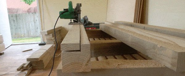
Step 1. Cut the frame pieces to length

- Cut the frame pieces to the lengths as given in the tables below. There is both a metric table followed by a standard (ft and inch) table.
Metric measurements (standard table next page)
| FOR | STOCK SIZE | LENGTH | QTY |
|---|---|---|---|
| base border frame | 90 mm x 90 mm | 1430 mm | 4 |
| [A] pillar | 90 mm x 90 mm | 2175 mm | 4 |
| base middle joist | 90 mm x 45 mm | 1250 mm | 1 |
| [B2] pillar | 140 mm x 45 mm | 2275 mm | 4 |
| [B] pillar | 190 mm x 45 mm | 2275 mm | 4 |
| [G] infill | 190 mm x 45 mm | 1030 mm | 4 |
| [C] pillar | 90 mm x 35 mm | 2175 mm | 8 |
| [H] middle head side | 140 mm x 35 mm | 1210 mm | 4 |
| [J] upper head side | 140 mm x 35 mm | 1140 mm | 4 |
| [E] sign holder | 190 mm x 35 mm | 1230 mm | 4 |
| [F] lower head side | 190 mm x 35 mm | 1280 mm | 4 |
| floor boards | 150 mm x 25 mm | 1370 mm | 10 |
Note: There are discrepancies between the metric table on the previous page and the standard (ft and inch) table on this page. There is good reason for that, so use one or the other but do not mix and match – i.e., stick to either the metric system or the standard system throughout the project.
Some stock sizes vary between the two. Puzzled? For further explanation, go to the ‘Explanations’ page.
Standard measurements (metric table previous page)
| FOR | STOCK SIZE | LENGTH | QTY |
|---|---|---|---|
| base border frame | 3½” X 3½” | 57¼” | 4 |
| [A] pillar | 3½” X 3½” | 87″ | 4 |
| base middle joist | 1½” X 3½” | 50¼” | 1 |
| [B2] pillar | 1½” X 5½” | 91″ | 4 |
| [B] pillar | 1½” X 7½” | 91″ | 4 |
| [G] infill | 1½” X 7½” | 41¾” | 4 |
| [C] pillar | 1½” X 3½” | 87″ | 8 |
| [H] middle head side | 1½” X 5½” | 48¾” | 4 |
| [J] upper head side | 1½” X 5½” | 45¾” | 4 |
| [E] sign holder | 1½” X 7½” | 49¼” | 4 |
| [F] lower head side | 1½” X 7½” | 51¾” | 4 |
| floor boards | 1″ X 6″ | 54¾” | 10 |
Step 2. Rip the relevant pieces to the required widths
- Rip (cut down lengthwise) the pieces that require ripping – namely pieces [B] pillar part, [B2] pillar part, [G]infill, and [E] sign holder.
- Rip to the widths given below.
Metric measurements (standard table below)
| PIECE | ORIG SIZE & LENGTH | RIP TO | QTY |
|---|---|---|---|
| [B] pillar part | 190 mm x 45 mm by 2275 mm long | 170 mm wide | 4 |
| [B2] pillar part | 140 mm x 45 mm by 2275 mm long | 125 mm wide | 4 |
| [G] infill | 190 mm x 45 mm by 1030 mm long | 155 mm wide | 4 |
| [E] sign holder | 190 mm x 35 mm by 1230 mm long | 155 mm wide | 4 |
Standard measurements (metric table above)
| PIECE | ORIG SIZE & LENGTH | RIP TO | QTY |
|---|---|---|---|
| [B] pillar part | 1½” x 7½” by 91″ long | 6½” wide | 4 |
| [B2] pillar part | 1½” x 5½” by 91″ long | 5″ wide | 4 |
| [G] infill | 1½” x 7½” by 41¾” long | 6⅛” wide | 4 |
| [E] sign holder | 1½” x 7½” by 49¼” long | 6⅛” wide | 4 |
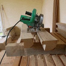
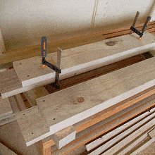
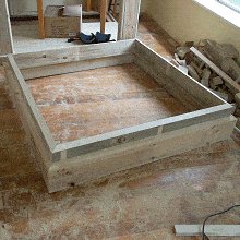
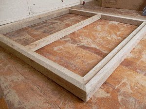
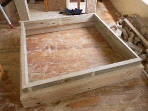
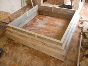
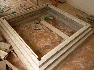
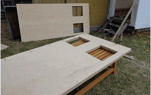
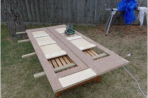
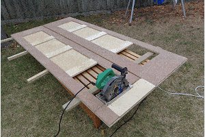
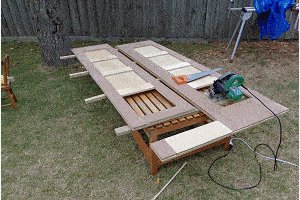
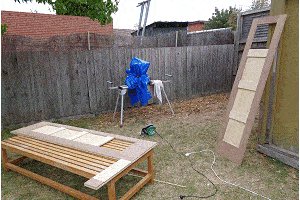
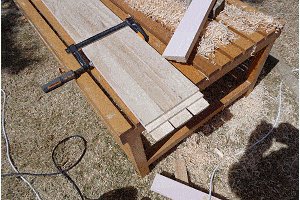
Step 3. Make the base
- The base consists of 4 pieces of 90 mm x 90 mm (3½” x 3½”) stock that are 1430 mm (57¼”) long for the frame, 1 piece of 90 mm x 45 mm (1½” x 3½”) stock that is 1250 mm (50¼”) long for the middle floor joist, and 10 only 150 mm x 25 mm (1″ x 6″) floor boards that are approximately 1370 mm (54¾”) long.
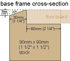
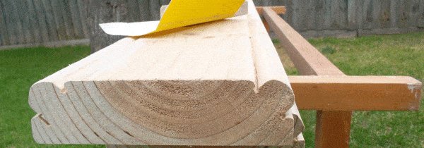
- 3.1. Make a rebate in the base frame to take the floor boards. Refer to the ‘base frame cross-section’ picture.
- 3.2. Cut the ends of the base frame pieces inwards 45°. Ensure that the measurement along the rise of the rebate is 1370 mm (54¾”).
- 3.3. Bevel the top edge along each frame member. Start the bevel 10 mm (⅜”) down and run it up on a 20° angle. Sand all pieces.
- 3.4. Assemble the floor base and add the middle joist.
- Do not add the floor boards just yet,
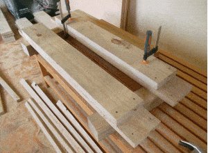
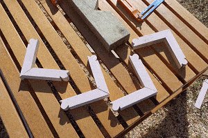
Step 4. Make up the pillars
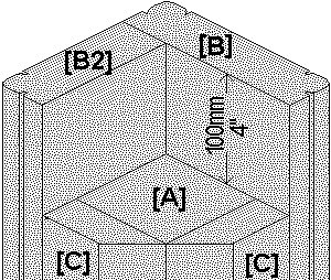
- Each pillar consists of a center post [A] and surrounding pieces [B],[B2], & 2 [C]s.
[A] is 90 mm x 90 mm (3½” x 3½”) stock 2175 mm (87″) long.
[B] is 170 mm x 45 mm (1½” x 6½”) stock 2275 mm (91″) long.
[B2] is 125 mm x 45 mm (1½” x 5″) stock 2275 mm (91″) long.
[C] is 90 mm x 35 mm (1½” x 3½”) stock 2175 mm (87″) long.
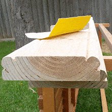
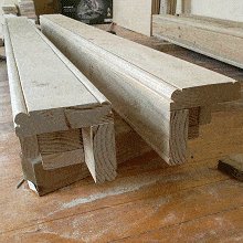
- Pieces [C] need to be mitred (angled) 45° down one side, and pieces [B] and [B2]need to be shaped (circular edges).
Shape the profile of pieces [B] and [B2]
- 4.1. Make a 7 mm (5⁄16″) deep cut, lengthwise down the face and edge 25 mm in from the corner.
- 4.2. Make another cut 16 mm (⅝”) in from the corner with the blade set on a 45° angle and the blade depth set to 7 mm (5⁄16″) – ending up with a trench the shape of half a V.
- 4.3. Round the corners of [B] and [B2] with a planer and sand paper to achieve as near as possible a 25 mm diameter round.
- Make up each corner pillar of the Police Box by joining piece [A] [B] [B2] and two [C]s.
Ensure one pair of corner pillars is made up in a mirror image of the other pair.
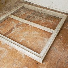
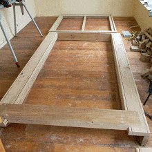
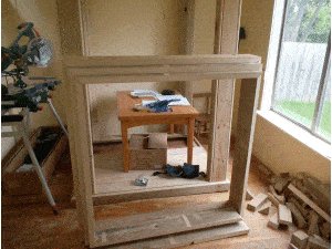
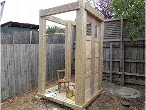
Step 5. Assemble and stand the frames
- Fix the infills [G] to the sign holders [E].
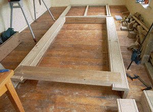
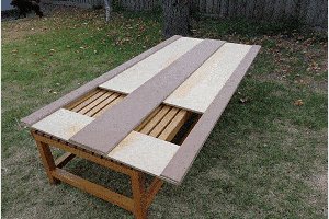
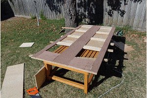
- On a flat surface, assemble and fix the front and rear frame units each consisting of two pillars, an infill/signholder piece, and a floor board.
- Then stand the front and rear frames units in place in the base frame. Screw the floorboard of each frame unit to the base frame and middle joist so that the screws can easily be extracted if the Police Box ever needs to be taken apart.
- Fix the side infill/signholder pieces to the front and rear frame units.
Screw the infill/signholder pieces to the pillars so that the screws can easily be extracted if the Police Box ever need to be taken apart. - Place and fix the remaining floor boards.
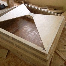
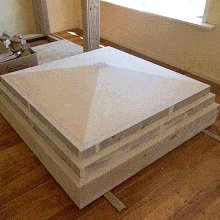
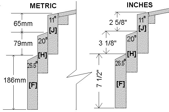
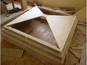
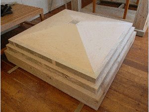
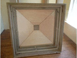
Step 6. Make the head (top section)
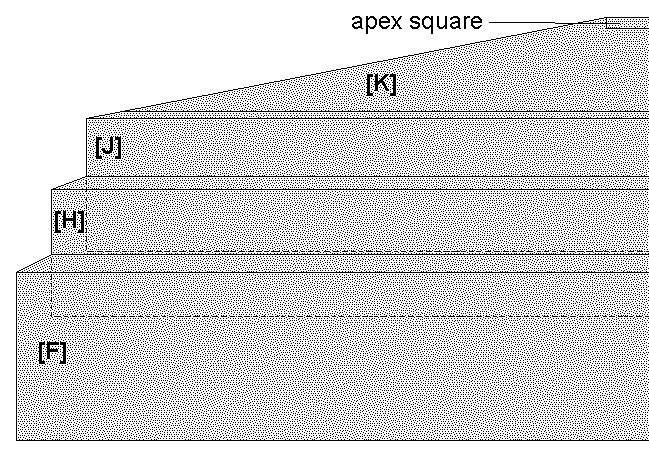
- The head consists of the apex square (a small shaped block at the very top), the roof panels [K], and three square box frames ([F], [H], [J],) that can fit into one-another – [H] can fit into [F], and [J] can fit into [H].
How to make it: Angle-cut along the top of all the frame side pieces as per the angles given below, and also cut a 45° miter at the ends of each piece. The overall lengths are also given below.
Lower head side [F] 1280 mm (51¾”) OA (check on job, measure where it’s to go in the frame structure). Cut a 26.6° angle along the top.
Middle head side [H] 1210 OA (check, measure where it’s to go in the lower head square). Cut a 20° angle along top
Upper head side [J] 1140mm OA (check, measure where it’s to go in the middle head square). Cut an 11° angle on top
- Make up the lower head square frame [F].
- Make up the middle head square frame [H] and fit it in the lower head square [F].
- Make up the upper head square frame [J] and fit it in the middle head square [H].
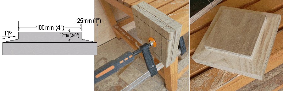
- Cut and shape the apex square out of a block of wood approximately 150 mm (6″) square and 35 mm (1½”) thick. Shape it as per drawing below.
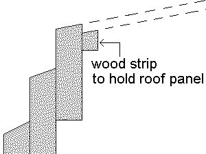
- Fix a wood strip around the inside of the upper head square to sit the roof panels on. Refer to the pictures below.
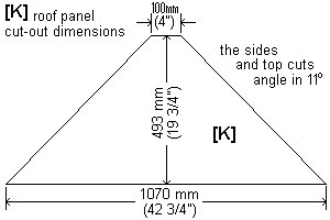
- Cut two roof panels 1070 mm (42¾”) long x 493 mm (19¾”) high with the sides angling in as shown in the drawing. Cut the sides and top so that they angle inwards 11° – ie., have the blade on your saw tilted 11° while you make the cut. (Check on job. Measure the actual required length along the bottom where the panel is to go and if necessary make adjustments).
- Assemble two roof panels opposing one another with the bottoms sitting on the wood strips and the tops resting against the apex square. They will be self-supporting. Glue and fix the panels to the apex square with a couple of screws at each meeting. Pre-drill the screw holes through the roof panels and screw down into the apex square.
- Measure the other two panels on site, specifically the length along the bottom, up the sides, and along the top. Cut and fix in place.

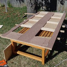
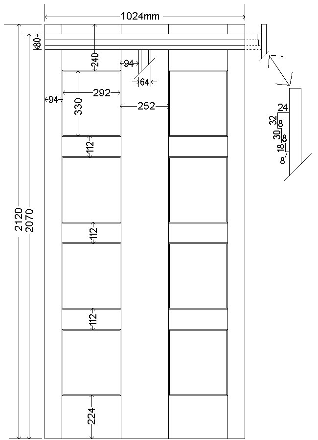
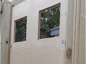
Step 7. Make the walls
- There are 4 walls. Three of them are identical, while the wall with the door differs.
- Each wall comprises of two sheets of plywood – one being the solid backing piece and the other being strips (stiles and rails) glued and screwed to the former.
- ‘Stiles’ are the strips that run vertically and ‘rails’ are the strips that run horizontally.
- Refer to the ‘fixed wall’ and ‘wall/door’ plans for dimensions and follow the instructions below.
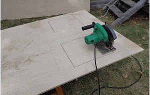
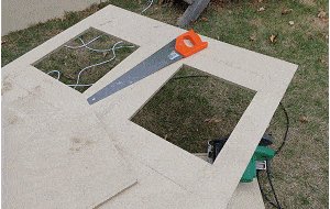
- Measure and mark on the backing piece panels where the stiles and rails are to go – and from there you can determine the windows.
- Mark the window cut-out holes which will be 12 mm (1/2″) bigger (all around) than the window markings.
- Cut out the windows with a circular power saw and a handsaw, or a jig-saw.
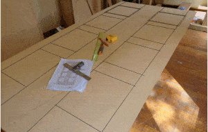
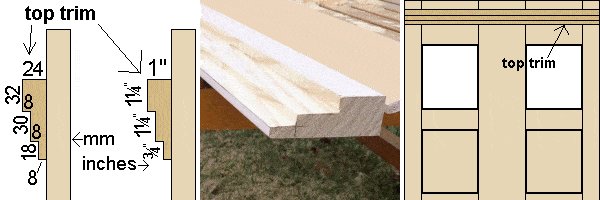
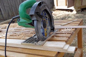
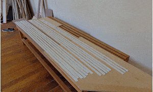
Cut the stiles, rails, and wall top trims
- Cut all the panel stiles and rails including the angles (25°). Cut the stiles to length but cut the rails oversize lengthwise. They can be measured and cut to exact length once the stiles have been fixed in place.
- Shape the top trim as per plan. Overall the trim will be 24 mm x 80 mm (1″ x 3¼”) with steps cut in it. Refer to drawing.
Fix the stiles and rails to the backing panels
Note: The stiles are the strips that run vertically and the rails are the strips that run horizontally
- Glue the stiles to the panels and hold them there with a coupe of tacks (small nails, pins) so the panels can be turned over without the stiles falling off or moving position during the ‘flipping’ process.
- Then screw through the panels into the stiles, pulling all the components tightly together and letting the glue do it’s work.
- Flip the panels over again so the face is on top. Then cut rails to fit between the stiles and fix them in the same way as the stiles were fixed. Sand all the panels.
- The layout of the panel with the door is different to that of the other three panels. Once this is sanded, cut out the door with a circular saw and a handsaw and sand the freshly cut edges.
- These photos illustrate the explanations above.
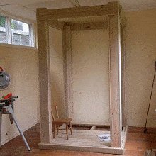
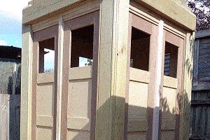
Step 8. Install the walls, head, and door
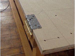
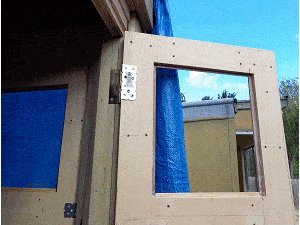
Fix one side wall and the front wall
- To only one (for the time being) side wall and the front wall (minus the door) add angle brackets, three to each side evenly spaced and a couple at the bottom. Refer to the pictures below.
- Fit one side wall (a removable wall, so do not add any glue or permanent fixings) and the front wall (less the door).
The front wall (minus the door) is a permanent fixture so glue can be added.
Drop the head in place
- With one side wall and the front wall in place, the unit is adequately braced to take the head. Drop the head in place. It should fit neatly into the main body frame and sit on pillar pieces [A] and [C].
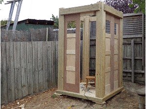
- Install the remaining two panels (walls) but first prepare them by adding the angle brackets (fixing brackets that tie the panel to the corner pillars).
- Fix the side wall in place without using any glue or permanent fixings so it is removable. Fix the back panel in permanently with both screws and glue.
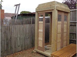
Fix the top trims
- Cut to length and fix the top trims to the tops of the panels with glue and screws.
- Note that the two side panels are made to be removable, so take care not to glue the trim to either the head or the side pillars. In other words, just glue between the trim and the panel, as the trim will be fixed to the panel so when the panel is removed the trim will be with it (and not stuck to the head or side pillars).
Door time
- Fix three 90 mm butt hinges to the door.
- Because the screws are going into the sides of the plywood it is a good idea to cover the hinge part against the door with an angle bracket that could be screwed into the side of the door as well as the back face. Have a look at the picture below. The reason? I’m not 100% satisfied with the holding power of screws screwed into the side of some plywood. Then hang the door.
Step 9. Shape and fix the mullions

- The mullions are the strips of wood that run up the center of the wall panels.
- Shape and fix the mullions. Refer to the drawing for the profile.
- Rebate the top of the mullions to fit over the wall top horizontal trim. See the picture below.
- This can be done by marking the shape and then cutting out by cross-cutting multiple times with the power saw blade set to the required depth.
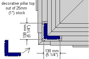
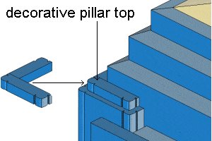
Step 10. Shape and fix the decorative pillar top pieces
- Shape, cut, and fix the decorative finishing pieces to the top of the outer pillars. These can be shaped in the same way as the pillar pieces [B] and [B2] were shaped. Glue them to the top of the pillars BUT NOT to the head, as the head is a removable item.
- Cut them out of 25 mm x 25 mm (1″ x 1″) stock.
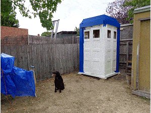
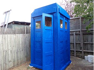
Step 11. Paint time
- Primer/sealer to the outsides and two coats of blue.
- This part is best left to you. You can get all the information on the type of paint, applications etc. from your local paint stockist.
The choice of colour is also up to you. There are many different variations of blue used for both the Police boxes and the TARDIS props.
There does not seem to be a standard blue color used for the many TARDIS props, so personal preference is probably the way to go.
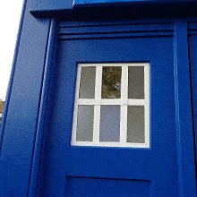
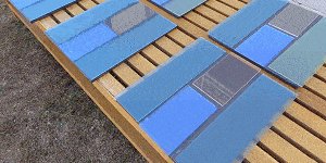
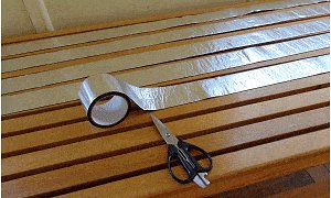
Step 12. Make the windows
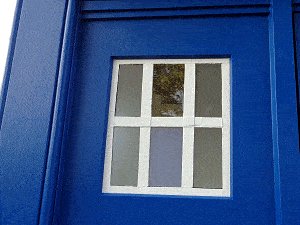
- There are 8 windows to make up. Each window consists of 4 panes of plastic glass (acrylic sheet) – specifically 2 side pieces 103 mm x 350 mm (4⅛” x 14″) and two middle pieces 103mm x 175mm (4⅛” x 7″) with the top middle piece being clear and the rest any color.
- The pieces are glued together and the joins overlaid with bars (strips) of 25 mm (1″) wide aluminium foil coated bituminous adhesive (flashing tape).
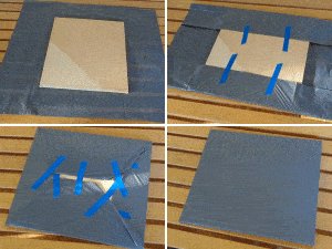
- Make a smooth working platform – Using the plywood off-cuts from the window holes (8 in all), cover them with a thin plastic sheet (plastic rubbish bags will do), fold the plastic underneath and hold it taut with tape. This is to make a pad / backing board so the window pieces can be glued together on them. The glue will not adhere to the plastic rubbish bags – that is the purpose.
- Use 3 mm (⅛”) thick acrylic sheet (plastic glass) cut to the following sizes and of varying colours:
- 16 of 103 mm x 350 mm (4⅛” x 14″)
- 16 of 103 mm x 175 mm (4⅛” x 7″)
- Lay out the acrylic sheet pieces in sequence with about a 6 mm (¼”) gap between them. Apply a thin bead of glue (Anglosol 700) in the gaps and then close the gaps. Because this glue is very powerful it can be harmful if not handled correctly – read the safety data notes that come with it or any similar type glue used for butt joining acrylic sheet.
- Once all the sheets are glued, leave them for around 5 hrs, then take them off the backing boards (so the air can get to the underside) and place them on some sticks to let the glue harden more overnight.
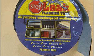
- Make the bars for the windows from a roll of flashing tape 75 mm (3″) wide by 10 m (33 ft) long. The tape is aluminium foil coated with a thick rubber/bituminous adhesive. It can be painted and is suitable for exterior use and sticks to just about anything.
- Cut the tape to workable lengths. The tape is easily cut with scissors or a craft knife. Using a pencil, measure and mark each length into three equal strips and cut them (by free hand) with a craft knife to end up with strips 25 mm (1″) wide.
- Then lay them on a flat surface and paint them white with a roller brush. Apply two coats.
- Apply the adhesive strips over the joins of the window panes and around the edges. The windows are then ready to be fitted.
- Run a bead of clear silicon sealant around the inside of the window holes and fit the windows in place.
- Hold them in position with a few temporary small nails partly nailed in around the edges until the silicon sealant cures and glues the panes in place.
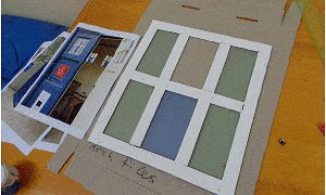
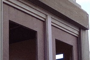
Step 13. Add the ‘police call box’ sign
- You will need a ‘police call box’ sign. Having a sign-writer do this for you is as good a way as any of getting it done, unless you are able to do it yourself.
- On a piece of acrylic sheet approximately 3 or 4 mm (1/8″ to 3/16″) thick have the sign prepared. Take that information below to the sign writer. You will need four signs.
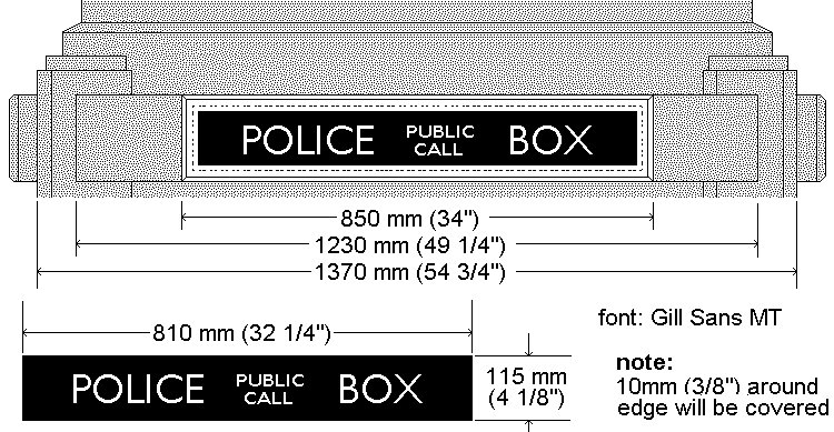
The trim around the sign
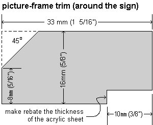
- Make and prepare 8 metres (28 ft) of trim to go around the ‘police call box’ sign. Shape according to the drawing.
- Once they are shaped, on a flat work surface, cut to make a picture frame around each sign. Paint them.
- Then fix the sign and surrounding trim (picture frames) in place on the sign holder pieces [E]
Step 14. Final touches (almost)
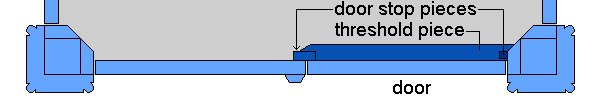
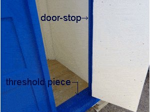
- Add a door-stop around the door opening and a threshold piece on the floor that the door will close into. This is to stop rain blowing or running in. Fix (approximately) 25 mm x 25 mm (1″ x 1″) wood up the hinged side of the door opening frame and 25 mm x 50 mm (1″ x 2″) stock to the other side.
- Use 19 mm x 50 mm (¾” x 2″) for the threshold piece. This is to stop rain-water blowing in and to give the door something to close against.
- You can probably get all of the above pieces from project off-cuts.
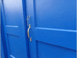
- Once the door-stops are in place, add a door handle and lock-set of choice.
Roof lamp Introduction
- This roof lamp is along the lines of the lamp that sits atop of the 1929 Mackenzie Trench design police box preserved at the National Tramway Museum in Crich, Derbyshire.
- It was, after all that police box that was the inspiration for The Doctors TARDIS.
Description
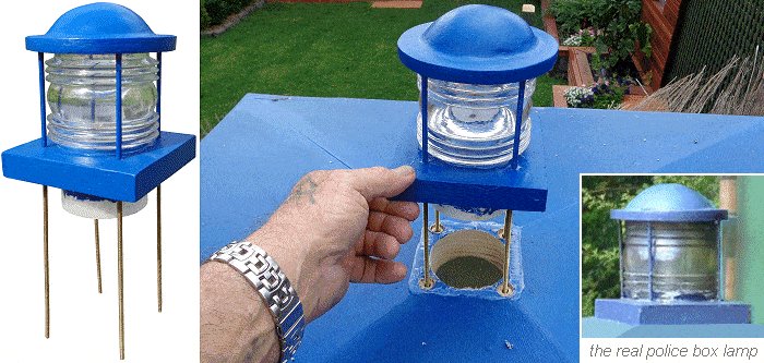
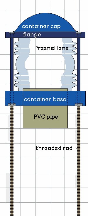
- This roof lamp is basically a lamp container consisting of a fresnel lens sandwiched between a cap and a square base piece.
- The base piece has a hole in the middle which accommodates a short piece of round PVC drain pipe.
- It is all held together with four threaded rods.
- The threaded rods protrude down past the square base piece in through the top of the TARDIS roof.
- From the inside, another square platform which carries the light bulb and socket is added to the threaded rod.
- The light bulb fits up through the PVC pipe into the fresnel lens. It can be adjusted up and down the threaded rod as need be.
- Once the lamp container is fixed to the TARDIS roof, the light is added (and adjusted) from inside the TARDIS box. That is very handy when a light bulb need changing.
Roof lamp Plans
Note: The grid spacings in the drawing represent 1 inch (25mm).

Sourcing the components
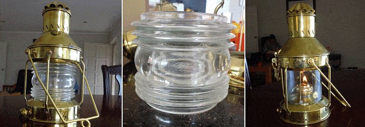
- The hardest part to find (for me, anyway) to make this lamp, was the fresnel lens.
I eventually saw one in a ship lamp (anchor light) that was sitting in the widow of a ship’s chandler.
I purchased the complete lamp just to get the lens but the lamp was not wasted as I replaced the fresnel lens with plain glass – simply a glass jar (from the supermarket) with the bottom cut off. It worked perfectly so I ended up with a working ships lamp as well as a fresnel lens for the TARDIS project. - The fresnel lens was 106mm (4 3/8″) outside diameter (at the widest part) and 90mm (3 1/2″) high.
The inside diameter was 76mm (3″) one end and 78mm (a little over 3″) at the other end. - All of the rest of the components I found without too much trouble.
Note: Since obtaining the fresnel lens, I have seen others at various places online including ebay.
Overview
Note: The grid spacings in the drawing represent 1 inch (25mm).
- The TARDIS lamp container consists of a fresnel lens sandwiched between a cap and a square base piece.
- The base piece has a hole in the middle which accommodates a small piece of round PVC drain pipe.
It is all held together with four threaded rods. - The container cap is a flange (round ring) with a dome in the middle.
- The flange is a ring, cut from a piece of plywood.
- The dome in the cap is a piece of dome-shaped wire mesh cut out of a cheap kitchen strainer (sieve).
- The ‘dome-shaped’ wire mesh fits in the hole in the middle of the flange. It is held in place with a bit of glue.
- Fibreglass covers the cap.
- The threaded wire protrudes down past the container base.
- The lamp container sits on top of the TARDIS roof and the threaded rod and the PVC pipe run through the roof.
- The lamp container is fastened from the inside of the roof and the light and light platform is also fitted from the inside of the TARDIS.
The lamp container cap
- For the dome in the cap I used the wire mesh cut out of a cheap kitchen sieve. For the flange I cut a ring out of a piece of 10mm (3/8″) thick plywood. I stuck the domed-shape wire mesh into the ring and fibreglassed over it.
- Instructions follow.
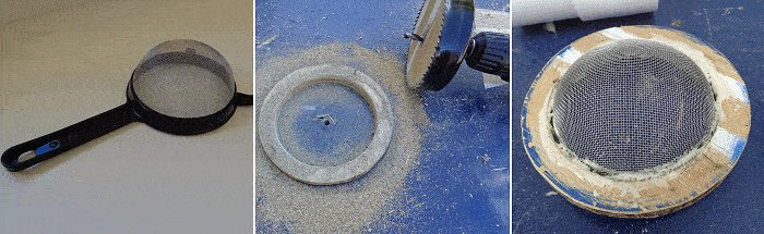
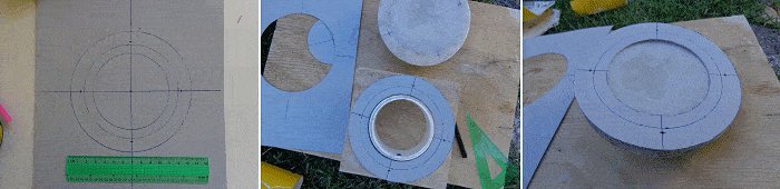
The flange
- Using a card board radial arm mark a circumference on a piece of 10mm (3/8″) thick piece of plywood with a diameter of 135mm (5 1/4″). Cut it out.
- Drill (or cut) a 105mm (4 1/8″) hole in the middle of it with a hole saw, jigsaw, or by any other means.
The dome
- Find an appropriate size cheap kitchen sieve (strainer).
- With a craft knife cut the mesh from the handle. Push it (the mesh) into the flange hole so it protrudes 32mm (1 1/4″) through the flange.
- Use the plywood center off-cut to hold the mesh against the flange. Sit it on a pillar (plastic container, jar, etc) and run a bead of glue between the mesh and flange around the rim.
- When the glue has dried, tidy up (sand excess glue) and with a craft knife cut off any excess wire mesh on the underside of the lamp cap.
Fibreglassing the cap
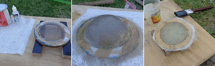
Fibreglass:
- Cut a piece of fibreglass mat big enough to cover the top of the lamp cap.
- Make up a mix of fibreglass resin and catalyst according to the instructions on the can.
- Apply a coat of mix to the top of the cap, lay the mat over the top of the cap and saturate with more fibreglass mix.
- The next day cut off the excess fibreglass around the perimeter using a fine tooth saw or blade and sand paper.
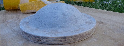
Next fibreglass the underside of the lamp cap in the same manner. - The next day cut off the excess fibreglass around the perimeter using a fine tooth saw or blade and sand paper and give the complete lamp cap a sand.
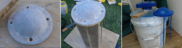
The lamp container base
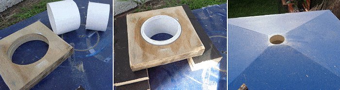
- For this use a piece of 24mm (1″) thick plywood 137mm (5 3/4″) square. Maybe glue two 12mm (1/2″) thick pieces together to get the required thickness.
- Also a short length about 64mm (2 1/2″) of PVC pipe with a diameter slightly smaller than the inside diameter of the fresnel lens. In this case, 76mm (3″) diameter.
- Drill a 76mm (3″) diameter hole in center of the plywood base piece and glue the PVC pipe in the hole, protruding 3mm (1/8″) out the top side and the rest hanging out the bottom. I used an adhesive sealant that would grip to both the PVC and the wood.
- While waiting for everything to dry, drill a 76mm (3″) diameter hole through the middle of the apex square at the top of the TARDIS.
- Make a hole template for the threaded rod. This is to mark all the necessary holes in the cap, base, roof, and light platform. Having a template ensures all the holes will be aligned.
- On a piece of card mark three circles.
- 1 @ 86mm (3 3/8″) diameter – the overall width (diameter) of the PVC pipe.
- 1 @ 106mm (4 1/8″) diameter – the overall width (diameter) of the fresnel lens.
- 1 @ 135mm (5 5/16″) diameter – the overall width (diameter) of the lamp cap
- Draw a cross from the middle and mark (on the cross lines) a point 3mm (1/8″) past the middle circle (the overall width (diameter) of the fresnel lens).
- Cut out along the lines of the most inner and most outer circles so you end up with a rim approximately 25mm (1″) wide.
That is the template to mark the holes for the four threaded rod pieces (the rods that hold it all together) on the cap flange, the base of the lamp container, the apex of the TARDIS roof, and the light socket support platform.
Threaded rod to the cap
- You will need four lengths of Threaded rod, 5mm (3/16″) diameter x 300mm (12″) long.
- Using the cardboard hole template, mark the holes for the threaded rod on the cap flange, the container base, and the apex of the TARDIS roof.
- Drill holes slightly bigger than the width (diameter) of the threaded rod through the hole marks.
Countersink to the depth of a nut, the top of the holes in the cap.
- Add a nut to one end of each of the four threaded rods.
- Sit the cap on top of a prop of some sort to enable the four threaded rods to dangle, once they have been inserted in the holes in the cap.
- Apply ample glue (fibreglass resin or similar) around the nuts, and also in the countersunk holes.
- Gently turn and twist and move the rods up-and-down to enable the glue to seep around the rod and through every bit of the holes in the container cap.
- Wipe off excess glue and leave to dry.
- Once dry, sand smooth and paint the cap, the base, and approximately 100mm (4″) of the threaded rods (the amount that will runs past the fresnel lens).
- Temporary tape the rest of the threaded rods so as not to get any paint on that part. The part of the rods that go inside the TARDIS roof need to be kept clean in order to take washers and nuts. In short, don’t paint any of the threaded rod that runs inside of the TARDIS.
Assemble the lamp container

- When all is dry, assemble the lamp container – Add a little sealant to the top and bottom rims of the fresnel lens.
- With the container cap in upside-down position, place the fresnel lens in between the four threaded rods and sit it on the underside of the cap, then slide the base down the threaded rods until it sits on the other end of the lens. Remember, everything is upside down at the moment. See the picture above.
- Then place washers and nuts on the rods underneath the base and tighten them. Voila! The TARDIS light container – all ready to place on top of the TARDIS roof.
- Countersink the top of the holes at the top of the roof to house the nuts and washers that are on the underside of the container base.
- The lamp container should now fit neatly into place on top of the apex square with the excess threaded rod running through the apex square into the TARDIS.
- Then place washers and nuts on the rods underneath the apex square (from inside the TARDIS) and tighten them.
Put in a light or two
- So! You have the lamp container in place, now you need a light. There is a lot of excess on the four threaded rods that hang inside the TARDIS.
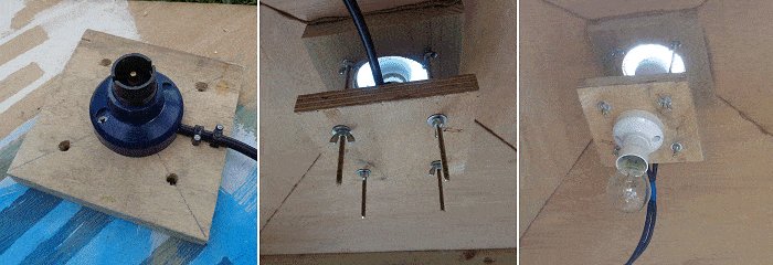
- Make a platform (for the light socket) similar to the container base – i.e., a piece of plywood 137mm (5 3/4″) square with four holes drilled to take the threaded rod, just the same as the container base.
Fix an appropriate light socket in the middle of the plywood piece and have an electrician (or qualified person) wire it for you.
Put a light bulb in the socket and push the plywood piece up (with the threaded rod going through the holes) until the light bulb sit at the required height inside the fresnel lens. Hold the platform in place with wing-nuts underneath. - There! Easy to adjust and easy to take out and change the light.
- You can also add another light socket to the underside of platform to light up the inside of the TARDIS if so required, although it would be best to run it off different power wires so that both lights are independent of one another.
The lights go on


Thank you so much for posting this!! My husband has been promising me for years now that he would build a TARDIS for me as my 50th birthday gift (I’ll be 56 in June), but used the excuse that he wants it to be just perfect and can’t do that without either seeing one in person ( not too easy in Colorado) or having plans//blueprints in hand. You’ve made my year!!! ?
Thanks so much again! You’re fantastic!
Got tips on obtaining a fresnel globe at the right dimensions? Almost everything I can find is a replacement lens for a Perko lamp which is about half as tall and wide as a typical TARDIS one would be.
I haven’t made this yet. Someone I know has a real UK Phone Box (the red ones), and I was originally thinking of helping him turn his into a TARDIS. Then it occurred to me to search for POLICE BOX instead of phone box, and that led me here.
Because of where I am, and the combined facts that, the average humidity is 90-100%, and we get oceans of rain pouring down all the time, I think it might be wiser to build an actual CONCRETE TARDIS, with a roof made of painted metal (I can also hide a drainspout too), just like most of the houses are built here.
Quite frankly, unless I cut extra thick wooden slabs from trees, wooden houses don’t last very long here. Bamboo works much better than wood.
Also, since I don’t have access to Time Lord tech to make the inside larger than the outside, I’ll just have to make mine slightly bigger than standard so I can use it as a toolshed.
Now to draw up the plans…
I find your instructions amazing. I like the real box but I think I will modify a few things to approach a few TARDIS design features. I’m also working out how to use the full plywood sheets at 1200 mm wide so I can fix them to the 45 mm faces of the columns rather than use the posts and angles in the column construction. I can cut some square wood the make up for 1200mm not being wide enough to 45 degree the play at the edges. I’m thinking of using the 2400 mm tall ply as the boxing of the first tier, maybe boxed inside for the right width to take the second. tier. To make up for not having the column posts in, I thought I’d attach some blocks to take the second/third tier weight. I really want my Police Public Call Box signs to light, so may box a gap to the inside rather than use the solid cross-pieces. My Fresnel is a 6” OD lantern flue as in the Crich boxes, so I have to modify the roof center square to be wider to take it. I like the outward opening door and may have both open since some old and new era episodes have a double out door config. So I really like your strip inside the doors for weatherproofing. Brilliant base design btw. I’m going to look for a bead router bit which is a quater circle with lips, similar to yours but not as pronounced a bead. I didn’t know about the acrylic edge bonding glue, so thanks. I may build a wood grid rather than the tape. I think I’ll try for an opening telephone cabinet door with a fold down shelf for versatility. I got a $300 table saw to make ripping and angles easier than a circular saw. Also, on the lamp front, I found a local (NZ) company who blows acrylic domes with flanges to the height needed. I plan to mount that on the upper wood circle once the rods are in. I think I can sheath the exposed rods in metal tubing, may work a treat. Everything depends on the actual wood dimensions so I’m taking it slow and remeasuring everything as I go. Not a cheap hobby but very fun and a great test for the brain and building skills. Thanks again.
Oh yeah, more lamp ideas. I’m going to try to hole saw a groove to receive the two lips of the fresnel lens into the wood plates, with an O ring to squeeze the lens/ wood interfaces watertight. Found some silicone O rings at 155 mm ID since the black rubber ones break down in UV.
Hi Les,
After making the Red English Telephone box in 2016/2017, I have just completed the Tardis. Thanks so much for the plans, they are awesome. In retrospect, I would have made the Police Public Call Box light up from the internal light. The Tardis was made for a 5-star resort as art and a walking destination. The photos show in constructed at my home and then moved to it’s final resting place.
Cheers
Derek
Hi Les,
Thank you so much for the plans. I need to build a fire-rated one as an enclosure for a residential elevator, so fire door, clad in type x wall board, and no windows, and these plans will help a lot. I did build one with no plans and dimensions I made up in my head, to cover a 4 foot hole in a deck. I was fortunate enough to purchase some lovely mahogany, and when it was done, I couldn’t bear to paint it. So I called it the “Uptown” Tardis. It will become the elevator enclosure on the second floor. It does not need to be fire rated.
Really scratching my head over part C. Why not leave off C and let the wall board be a little wider?
The way the pillars just sit on the floorboard is a little suspect as well. I’d like to see the post go through and screw to the base.