Contents
Introduction
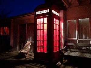
The K2 telephone kiosk is arguably the most iconic British telephone box of all time.
K2 stands for Kiosk 2, and was the second booth to be deployed around London. That was in 1926. The K2 design was the result of a competition in 1924. A design submitted by Giles Gilbert Scott was selected but some of his specifications were changed, such as color, materials used, and a few other minor details.
The original K2 Telephone Box was made out of cast iron, was 3ft 6in wide and deep, stood 9ft 4in in height and weighed around 2756 lb (1250kgs). It took over from the K1 (Kiosk 1) which was a concrete structure.
Today, the remaining K2 Telephone Boxes in London are beautiful landmarks and are mostly protected Grade II Listed Buildings; the grade II category meaning “buildings that are of special interest, warranting every effort to preserve them”.
I, along with many others think that the red British K2 Telephone Box is a marvelous structure – why wouldn’t you want one in your property?
Many people sport a red telephone box in their home or garden as a sort of quirky accessory. They are used as tool sheds, decorative garden structures, shower boxes, even as fully functioning telephone boxes. They are also found in bars and restaurants around the world adding a little touch of Britain. Sometimes they can be found in somewhat deformed states, after having been transformed by artists who’ve given their unique spin on these iconic booths.
I had to have one.
I decided to make one – out of wood, plus whatever.
This was to be the most eagerly anticipated project I had ever undertaken.

K2 telephone box
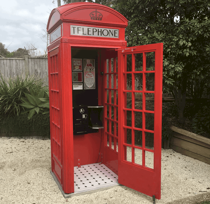
$5.00Of all the projects that I have made over the years, my red English Phone Booth created the most interest.
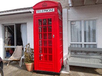
It was a project I thoroughly enjoyed building. Originally I was going to place it in the garden as a feature, and maybe use it to house a few garden implements or something. But, throughout the course of construction (which took a while as I only worked on it casually) it spurned far more interest, curiosity and comments from friends, visitors and passersby than any other project I had undertaken. My wife Jenny said, why not place it in the front yard against the house for all to see?
In fact why not make it a fully functional working red telephone box?
So I decided to go the whole hog, and have a working light and working telephone inside it.
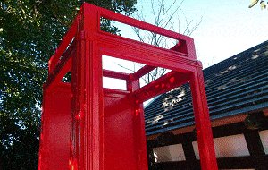
My take on the K2 red telephone box.
I didn’t want my K2 red telephone box to be an exact replica of the real version.
I wanted some lines to be accentuated so that a trained eye could pick up the intended differences, while it still being unmistakably a take-off of the K2 telephone box.
For starters, the original K2 booth was made out of cast iron, while mine is mostly wood.
The original K2 booth was 9ft 4in tall; mine is 8ft 7in tall. However, that’s not a lot of difference in size – it’s still a pretty big box.
Then there will be the subtle line changes that put my mark on it, while still giving it the distinct K2 flavor.
Come with me as I take you through a step-by-step account of how I made my take-off of the red British K2 Telephone Box. I’ll share my methods and techniques, and add the occasional expert contribution, along with a bit of helpful reader input.
To a certain degree this is a live document because of the ability to access ongoing reader input.
The size of the thing
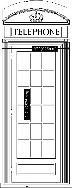
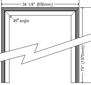
My version stands 8′ 7″ (2575mm) high and is 37″ (925mm) square. It is a big box, but still not quite as big as the original.
The original K2 Telephone Box was made out of cast iron, was 3ft 6in (1050mm) wide and deep, stood 9ft 4in (2800mm) in height and weighed around 2756 lb (1250kgs).
So all in all my version looses about 11″ (275mm) in height and about 5″ (125mm) in girth.
I must point out that the K2 model was the tallest model made. The K6, a far more common red booth, stands 8ft 4in (2500mm) high. That’s a good foot (300mm) shorter that the K2.
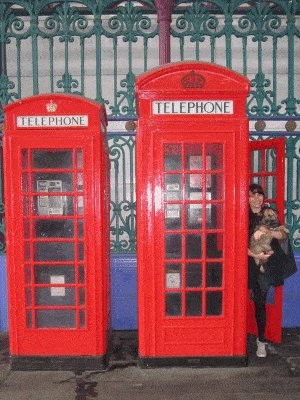
The photo shows the difference in height between the K6 and K2 telephone kiosks. The photo was taken at Smithfield Market in London. That is Jacqui, one of my daughters, holding her dog Polly, in the K2 phone box.
About the measurements used
The dimensions in this project are given in both imperial and metric.
All measurements are given in feet and/or inches first, followed by millimeters (mm) in brackets (). For example: 2″ x 4″ (100mm x 50mm)
For rounding off purposes, the imperial sizes are not an exact match to the equivalent metric sizes.
For example, something built using the imperial (ft and in) measurements will be approximately 1.6% larger than the same item built using the metric measurements. The imperial measurements are more suited to North America. The metric measurements are more suited to Australasia.
Most countries that use the metric system generally put the bigger numeral first, such as 100×50 (mm), whereas those that use the imperial system generally put the smaller numeral first, such as 2″ x 4″ (inches).
Also, both nominations have different finished (actual) sizes. That is, once the wood has been dressed (planed or surfaced).
For example: 2″ x 4″ (100mm x 50mm) when dressed will be more like 1½” x 3½” (90mm x 45mm).
Don’t worry about the irregularities between the two; just use all one or the other.

Overview – the eight chapters
This documentation consists of eight chapters.
The first seven are the seven different stages of constructing the K2 telephone kiosk. Chapter eight is where you will find all the plans.
The seven stages of construction are: the head, the body frame, the neck and sign, the door and windows, the base and a bit of painting, putting it all together, and the ceiling and night light.
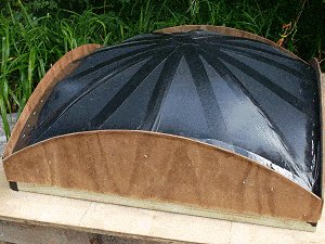
I constructed the head out of wood, hypertufa (very lightweight concrete), and fiberglass. I had never worked with the latter two before but found using both to be fun and easy.
The rest of the project was pretty much basic woodworking with a little bit of forethought.
Next is a map (drawing) of the phone box with part identification. From there you can jump straight to information about any particular part of the phone box – a visual index – and that is followed by a step-by-step account of how I made the phone box.
All the plans are in chapter eight, but some will be shown in the appropriate places as we follow the path of constructing a red British K2 Telephone Box.
A visual index
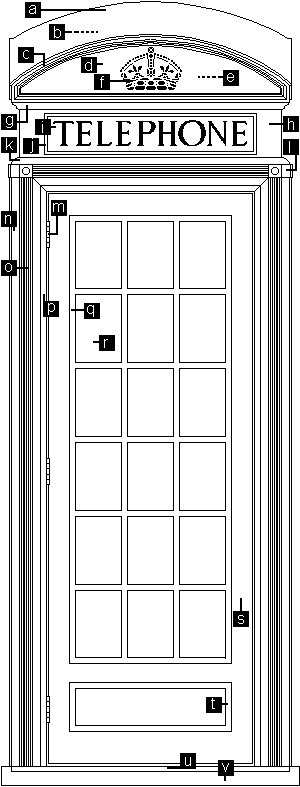
Here is a map (drawing) of the phone box with part identification. By clicking on any of the links below you can jump straight to information about that particular part of the phone box.
[a] Roof
[b] Inside roof frame
[c] Side-cover trim
[d] Head side-cover
[e] Head side-frame
[f] Crown
[g] Scotia
[h] Neck
[i] Sign
[j] Sign frame
[k] Horizontal quarter round
[l] Shackle
[m] Hinge
[n] Vertical quarter round
[o] Frame and corrugated profile
[p] Trim around the openings
[q] Muntin bar
[r] Window pane
[s] Door stile
[t] Decorative door/window trim
[u] Floor
[v] Base
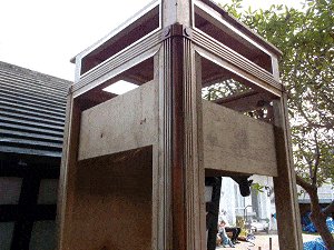
Chapter 1: The Head
Overview of the head
The head was the most involved (and probably the most exciting) section of the project. It touched on four crafts: woodworking, lightweight concreting, fiberglassing, and painting.
The head was made up of the following (in the order of making):
● The side-frames, out of 2″ (50mm) thick wood.
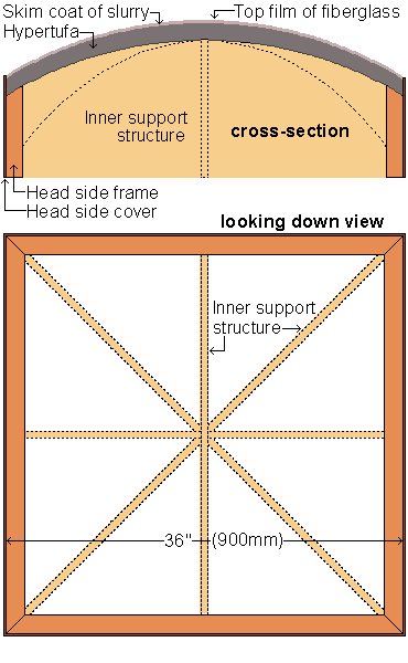
● The inner support structure.
The inner support structure comprised the cross-section and diagonal-section pieces that were used to support the roof until the different applications (hypertufa, slurry) cured or set.
Most of this was then be removed.
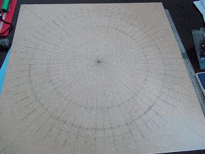
The inner support structure from a looking down point of view was sort of like an eight-spoked asterisk ✳ .
● A layer of hypertufa (lightweight concrete) about 1¾” (45mm) thick.
● A thin skim of slurry (a paste-like mixture of cement and water).
● The side-covers, out of 3/16″ (4mm) plywood.
● A thin cover (roof only) of fiberglass.
Getting started
The first thing that I did after looking at a trillion photos, was to play around with design on paper.
I eventually came up with my final working drawings. My plans.
Step 1.1. The head side-frames.
The head side-frames were made out of 2″ x 8″ (200mm x 50mm) wood. They formed a 36″(900mm) square. The actual or finished size of the wood once dressed (planed or surfaced) was 1½ x 7½ (190mm x 45mm).
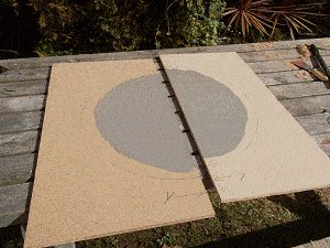
I cut four pieces of 1½ x 7½ (190mm x 45mm) wood, each slightly longer than 36″(900mm). Each piece needed a bevelled curve (compound cut) cut along the top edge.
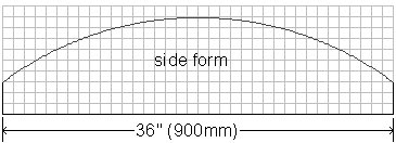
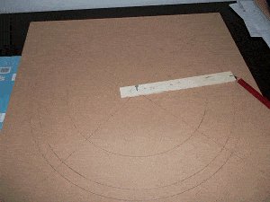
I needed to make a pattern in order to mark the curved shape on the wood.
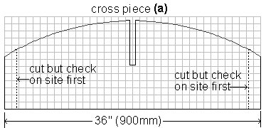
I drew a plan on a grid with the line spacings representing 1″ or 25mm. This made it easy to transfer the shape onto a piece of cardboard in real size, cut the cardboard, and then use that as a pattern to mark the wood.
Below is the grid plan with the line spacings representing 1″ or 25mm.
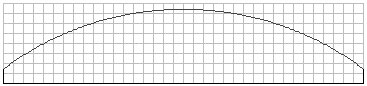
All you need to do to make a pattern is to get a piece of cardboard 8″ x 36″ (200mm x 900mm) and draw a grid with the line spacings 1″ or 25mm apart. Then draw a curve, as shown above, onto the cardboard using the grid lines as points of reference.
For your information; the diameter of the curve is 5ft (1500mm).
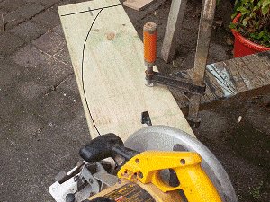
Once I marked the wood, I clamped each piece securely to a saw horse for cutting.
The curve and angle was easy enough to cut (doing a few runs) using a circular power saw with its blade tilted 30° off square.
Note: The angle cut is outwards from the mark line – not inwards. See the drawing below.
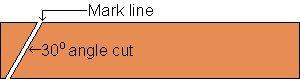
Step 1.1. continued
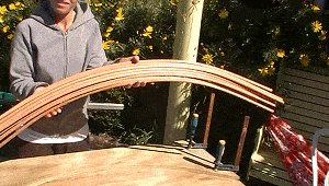
And this (in the photo) is what a piece looked like after the curve had been cut.
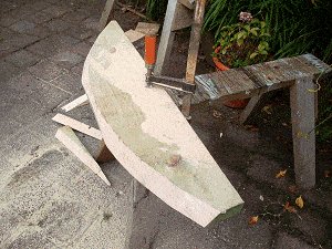
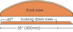
Once the curves along all the four pieces were cut, I then cut a 45 miter (angling in) at both ends of each piece.
See the drawing below.
Then, on a flat surface I fixed the four head side-frame pieces together with glue and nails ending up with a 36″ (900mm) square.
Refresher note: The size of the wood I used for the head side-frames was 2″ x 8″ (200mm x 50mm) which is pretty much a common size, but that is the nominal size – i.e., the size that the wood is called. The real or actual size is more like 1½ x 7½ (190mm x 45mm).
In other words the wood starts out at 2″ x 8″ (200mm x 50mm) but by the time it is dressed (planed, smoothed, or surfaced) it finishes up being more like 1½ x 7½ (190mm x 45mm).
Most smooth finished wood is the latter size.
If wood is actually the bigger size (the size prior to being dressed) it is usually called ‘rough sawn’ or rough lumber.
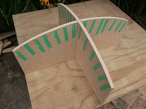
Step 1.2. The head inner support structure.

The inner support structure comprised of cross-section and diagonal-section pieces that were used to support the roof until the different following applications (hypertufa, slurry, fiberglass) cured or set.
I made the pieces out of ¾” (18mm) custom board, but any similar type of board would have done, such as plywood.
There would be two cross-section pieces interlocking in the middle and four diagonal-section pieces fitting neatly into each quarter, running from center to corner. The pieces would give the profile of the dome.
I needed to make a pattern for each piece to mark the shapes onto the custom board.
I drew the plans for each piece onto a grid where the line spacings represented 1″ or 25mm. This made it easy to transfer the shapes onto pieces of cardboard in real size, cut the cardboard pieces, and then use them as patterns to mark the custom board.
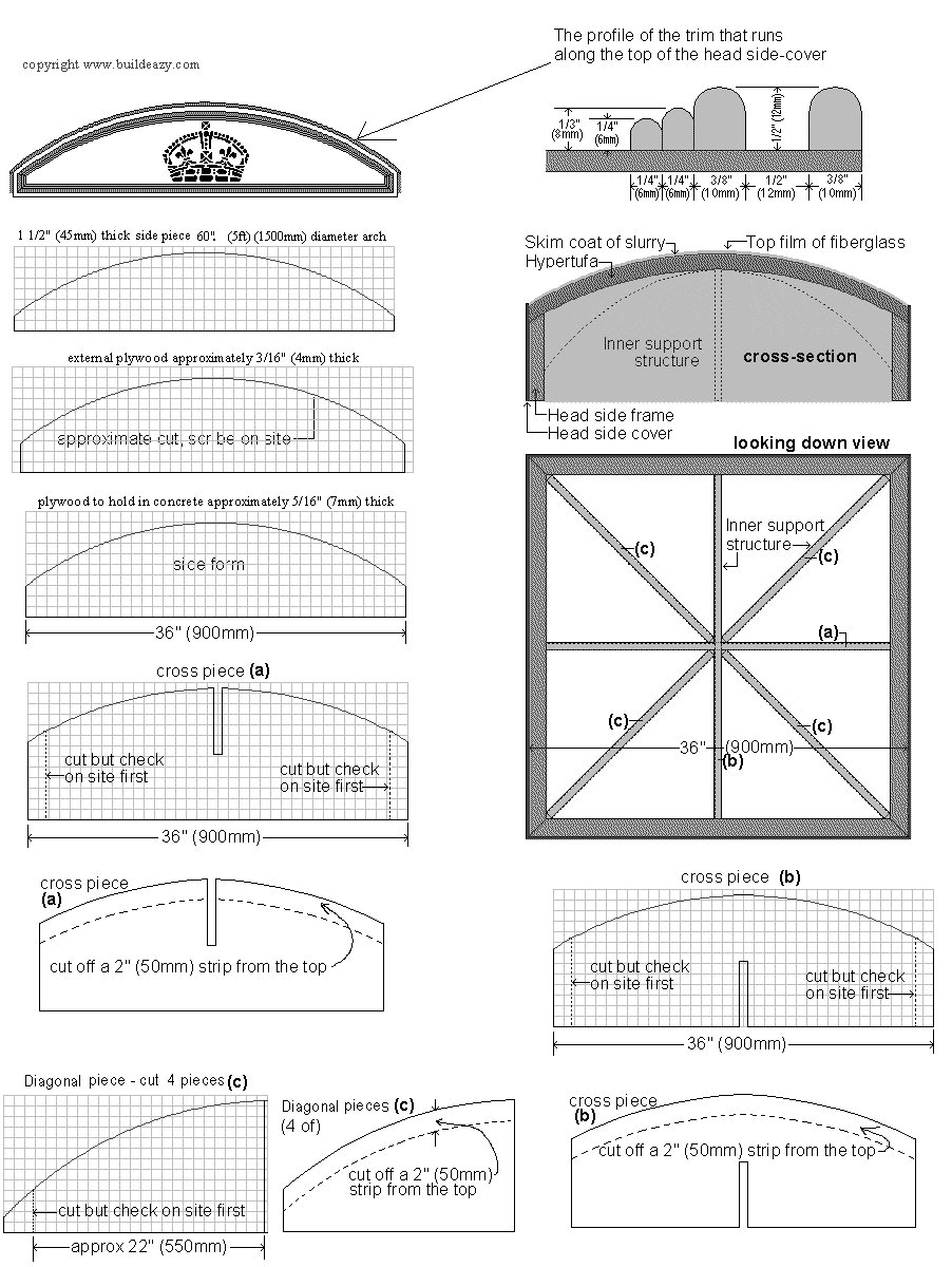
Below are the plans I used where the line spacings represented 1″ or 25mm.
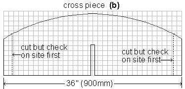
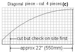
All you need to do to make the patterns is to get 4 pieces of cardboard 25″ x 13″ (625mm x 325mm), and 2 pieces of cardboard 36″ x 13″ (900mm x 325mm), and draw a grid on each piece with the line spacings 1″ or 25mm apart. Then draw the shapes as shown above onto the cardboard using the grid lines as points of reference.
Note: Although various relevant plans are shown throughout the course of these instructions, they are also all grouped together in Chapter 8.
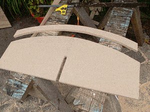
Step 1.2. continued
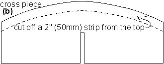
Once I cut all the head inner support structures ( the two cross-pieces and the four diagonal-pieces) according to the dimensions given on the previous page, I needed to cut them all again.
A two inch (50mm) strip had to be cut off the top of each piece and then taped back on again.
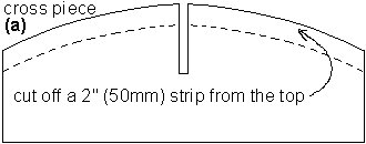
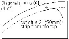
Why? Why cut off a 2″ (50mm) strip and then tape it back on again?
Because once all the ensuing applications had cured i.e. the hypertufa and fiberglass, then the lower portion of all the cross-section pieces and the diagonal-section pieces were removed, leaving only the top 2″ (50mm) ribs in place on the underside of the roof.
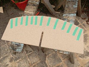
Photos above: A two inch (50mm) strip was cut off the top of piece cross-section (b) and then taped back on again.
The same was done to all the cross-section and diagonal-section pieces.
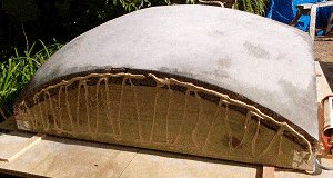
When the head was finished, the lower portions were removed, leaving just the ‘ribs’ in place on the underside of the roof.
Step 1.2. continued
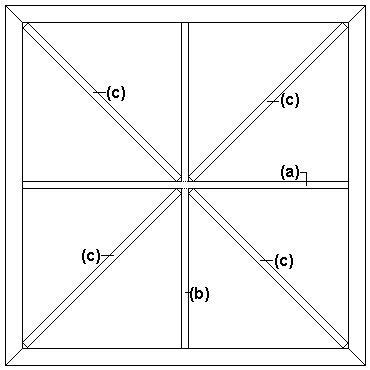
When all the cross-section and diagonal-section pieces were prepared I began to insert them.
First off, the slot in cross-section piece (a) slipped into the slot in cross-section piece (b), making a cross.
I placed the ‘cross’ inside the head side-frames and then I dropped the four diagonal-section pieces (c) into each quarter, running from center to corner.
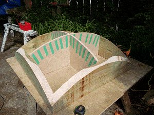
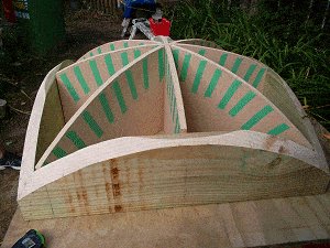
At that stage the profile of the dome became evident.
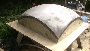
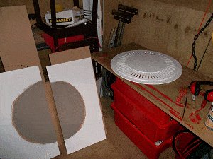
I was looking forward to applying a batch of hypertufa but first there was a form to make.
A form is a mold of sorts; something to hold in the hypertufa until such time as it cures (sets).
Step 1.3. The form (mold) for the hypertufa.
Hypertufa (in a sense) is a lightweight concrete.
In order to cover the top of the head with hypertufa I had to make something to hold it in place until it cured (set). This involved covering the current structure with polythene (plastic) sheet to stop the hypertufa falling through the support structure, and also fixing a wall (form) around the sides to stop the hypertufa running over the sides.
I stapled and taped some polythene (plastic sheet, such as plastic rubbish bags) over the top of the head and pulled it tight.
Then I ran some tape over the polythene along the top of the inner support structure frame-work, and stapled that as well to ensure extra strength
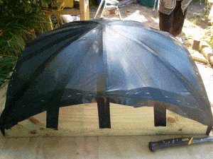
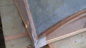
Then I made a form around the sides of the head to contain the hypertufa (lightweight concrete).
I made the forms out of spare plywood that was 5/16″ (7mm) thick. The forms were discarded after use.
Below is the pattern for the temporary form pieces that went around the sides of the head.
The line spacings on the grid above represent 1″ (25mm).
Once cut, the form pieces were screwed to the sides of the head. The top of the forms sat a little over 1½” (40mm) higher than the sides of the head.
Note – release agent: Before any hypertufa was poured, I brushed release agent on the inside of the plywood form so that the hypertufa would not stick to the form. The release agent was a mixture of diesel and used car oil.
Step 1.4. Hypertufa
Hypertufa (in a sense) is a lightweight concrete.
Some expert advice: The success of hypertufa depends on the consistency of the mix and the amount of attention paid to the curing process.
Okay! Having read stories about other people’s less than perfect hypertufa attempts resulting in cracked and crumbling end results, I decided to take the above advice very seriously.
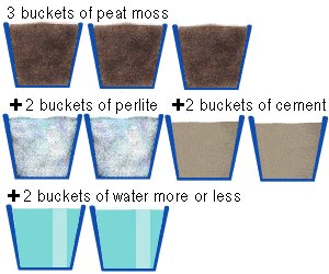
My hypertufa mix
● 3 buckets of peat moss
● 2 buckets of perlite
● 2 buckets of cement
● 2 plus buckets of water (more or less)
The peat moss and the perlite was bought from a garden center and the cement from a building supply store.
Some safety stuff: Breathing in any of the above ingredients (except the water) is not good for your health. Wear a mask, goggles, gloves, and appropriate clothing. The ingredients are very light and any wind or mixing disturbance will cause the dust particles to float through the air.
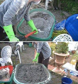
The mixing
The above dry ingredients were poured (carefully) into a wheelbarrow and mixed together with a spade.
Then the water was poured in slowly – about 1/2 of a bucket at a time – and the mixing continued.
It was mixed with the spade from underneath and folded over. Mixing and adding water continued until the mix was a uniform consistency: wet enough without puddling and able to be spread without crumbling.
Tip: A smaller spade or shovel is easier to work with than a bigger one.
Step 1.4. continued
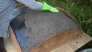
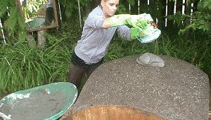
Placing the hypertufa
How thick? – At least 1½” (40mm) thick.
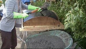
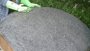
By the way, the girl in the photos is one of my daughters, Angela, who enjoyed giving a helping hand from time to time.
We (she) commenced shovelling the hypertufa into the head form, and spread it around with a gloved hand.
At this stage it was just half filled – a layer about 1″ (25mm) thick.
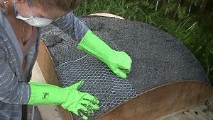
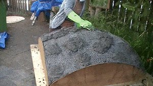
Angela placed sheets of galvanized bird wire mesh on top of the (half filled) hypertufa.
The sheets of bird wire were cut to about 12″ (300mm) squares and slightly overlapped. If we’d used a full sized sheet it would have been too hard to achieve the dome shape.
Then a few hypertufa patties were placed on the bird wire to hold it down.
Notice in the photo that Angela is wearing good waterproof gloves. These are a must when working with cement-based applications due to the caustic nature of the beast (the cement, not Angela).
Then it was just a matter of topping up with hypertufa and smoothing it over with a gloved hand.
I realized then that the hypertufa finish would not be good enough as a final finish for the head. I was thinking that after an initial curing period I would add a skim coat of slurry – icing on the cake.
Step 1.4. continued
Hypertufa – The curing process
This is probably the most crucial segment of the hypertufa application.
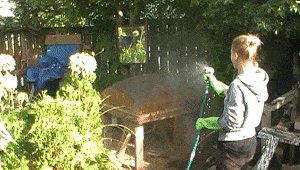
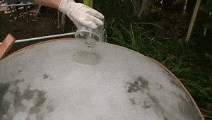
Curing time – The longer hypertufa is left to cure (set) the better. I kept the hypertufa moist at all times during the curing process, which went on for ten days. It was easy to contain the moisture with a polythene (plastic) sheet covering the hypertufa.
Once the hypertufa had been poured, we waited about four hours until the mix had just firmed enough to allow a sheet of polythene (plastic) to cover it without damaging the mix.
Through that initial time we kept the hypertufa moist, mist spraying it a couple of times.
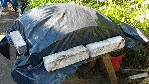
Why cover it with polythene?
As mentioned before, hypertufa must be kept moist during the curing process.
One of the main culprits that causes the hypertufa to dry out during the curing period is evaporation.
Obviously this is even more of a problem in hotter temperatures.
Enter the polythene cover –
By covering the hypertufa with polythene the moisture in the mix can’t evaporate because it can’t get out.
Therefore, all the drying out is from a chemical reaction that happens between the cement and the water called ‘hydration’.
I kept the hypertufa covered for a total of ten days. (Note that on day 4 I added a skim coat of slurry – see Step 1.5.).
Once a day I lifted the cover for a look-see. Everything was always still moist but I would give it another hose anyway ( a good old saturation) while the cover was off. Then I would put the cover back on again.
Sometimes in the heat of the day, the cover got pretty hot. But that didn’t seem to matter.
Step 1.5. Slurry
A skim coat of slurry
Slurry is a paste-like mixture of cement and water with maybe a little bit of fine sand if you want to add a bit of substance.
As mentioned on the previous page, I kept the hypertufa moist and covered with polythene for ten days (the curing period).
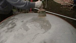
On day 4 of the curing period we added a skim coat of slurry.
Because the hypertufa was going through the curing period, it would adhere well to the slurry.
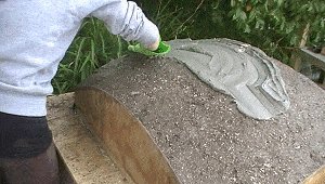
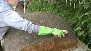
First Angela gave the hypertufa a bit of a brush to get rid if any loose stuff.
Then she mixed 3/4 bucket of cement, 1/4 bucket of fine sand, and added water as needed to a paste-like consistency.
And then she poured it onto the hypertufa.
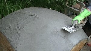
She then spread the slurry about with a gloved hand and smoothed it off with a trowel.
The hypertufa had a roughish type texture and the slurry was like the icing on the cake.
The slurry was just thick enough to cover the rough texture of the hypertufa.
Once the slurry had been smoothed, we ensured that it stayed moist while we waited about three hours for it to firm enough to allow the sheet of polythene (plastic) to go back on.
Of course, firming times could vary greatly depending on climatic conditions.
So! To recap the curing process
● The curing process lasted ten days.
● The hypertufa was kept moist at all times.
● The hypertufa was covered with plastic sheet to prevent evaporation.
● The hypertufa got hot at times, but that did not matter.
● The cover was lifted once or twice a day to ensure all was moist and to spray again.
● On day four the slurry was added.
● The cover was put back on and lifted once or twice a day to ensure all was moist and to spray again, and so on until the end of the curing period (day 10)
Note: Maybe the above curing procedure could have been a bit of an overkill, but it certainly worked.
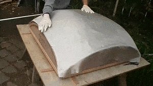
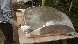
Off with the formwork
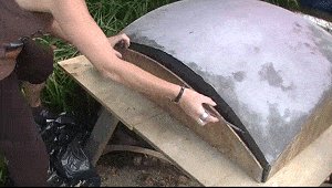
That was easy enough to do: just a matter of undoing a few screws.
The form broke away cleanly because we had applied release agent to the form prior to pouring the hypertufa.
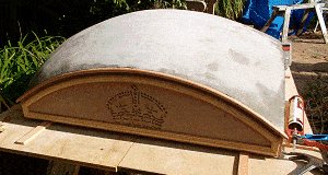
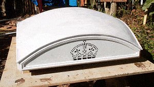
It was pleasing to see how the slurry-coated hypertufa looked at the end of the cure period and after the form was taken off. A successful pour.
Although the curing period took ten days, the time wasn’t wasted. I wasn’t sitting around for ten days scratching my nose waiting for the curing period to finish. I was getting on with other sections of the project.
Next on the agenda: The head side-covers and the crown
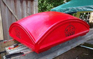
Step 1.6. The head side-covers and the crown
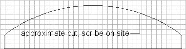
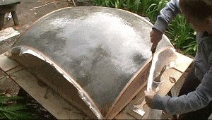
Using clean 3/16″ (4mm) thick plywood we cut four pieces 38″ (950mm) long x 10″ (250mm) high, one for each side of the head. Each piece was held against a side of the head, the curved line of the roof edge was scribed (marked) onto that piece of plywood, and then cut.
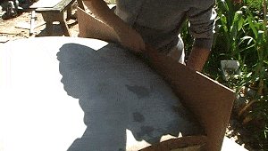
The trim around the side-covers
I managed to source some 1/4″ (6mm) and 3/8″ (10mm) thick bullnose (rounded one edge) cedar, from which I was able to rip the required widths for the trim that I used around the head side-covers. Mind you, even if I had only been able to get rectangular profiled wood (probably more common), I could’ve still sanded the edges round.
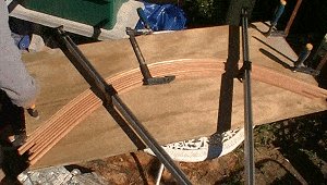
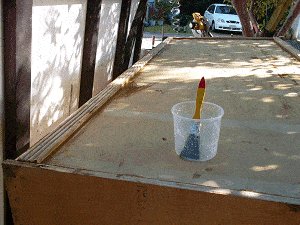
I bent the trim to the curve of the side-covers using clamps, and blocks of wood, and anything else needed to do the trick to hold them in place.
Would they stay bent the next day when I took the clamps off?
Case study
The following day – I released the clamps to find that the wood had only bent marginally.
I put the clamps back on and poured boiling water over the bent pieces, about 5 larger-sized pots. Then left the wood as it was (still clamped) out in the weather for a couple of days.
Then when the clamps came off? The curves were over 90% or the required shape. That was good enough.
The crown

Step 1.6. continued
So far we had cut the head side-covers to shape and bent the trim, but we had yet to fix the trim onto the side-covers.
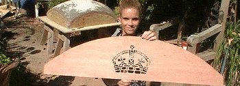
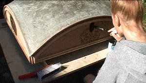
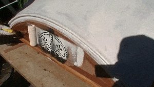
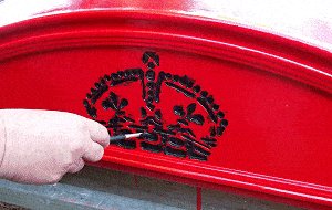
First, the crown had to be etched into the side-covers.
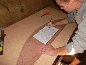
I made a pretty good copy of the K2 crown and made a full-size pattern in a printable file so I could print out a copy anytime I liked and (using carbon paper) trace the pattern onto the plywood side covers.
By clicking on the crown image you will get a full-size image that can be saved to your computer.
Angela marked where the trim pieces were to go on a side-cover.
This was to ensure that the crown would fit between the trim rather than overlapping it.
She then printed out a full-size drawing of the crown, and (using carbon paper) traced the pattern onto the plywood side-cover.
Ditto with the other three side-covers.
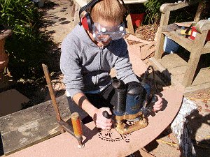
Once marked, the head side-covers were fixed securely on a work platform and using a router, the K2 crown pattern was cut out.
This was fairly slow work because of all the nooks and crannies in the pattern.
Step 1.6. continued
Fixing the trim to the side-covers
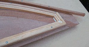
The side-covers were placed on a sheet of soft board.
The trim pieces were fixed to the side-covers with glue and small nails.
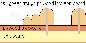
The nails went right through the plywood and into the soft board.
When all the trim pieces were glued and nailed, the side-covers were lifted off the soft board, turned over, and the protruding nail points were bent back against the back of the side-covers.
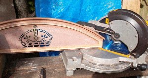
At that stage both the side-covers and the topmost trim were left slightly over length.
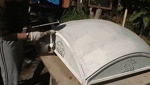
The side-covers were then held in place against the head, marked for length, and cut with a miter saw.
The side-covers were ready to be fixed to the head.
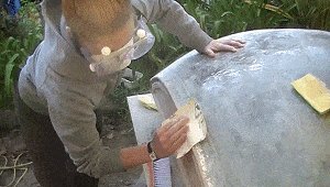
Plenty of glue was applied to the sides of the head as shown in the photo.
I used both glue and nails to secure the side-covers to the head.
I was very careful the glue did not ooze through any of the crown impressions and fill them up –
that would be sort of defeating the purpose.
Next on the agenda?
A dabble into fiberglassing.
Step 1.7. Fiberglass
For our first venture into fiberglassing we found it a very easy craft to master, or at least within the realms of our requirements.
We used an epoxy resin and some fiberglass cloth. It basically entailed brushing on a coat of epoxy resin, laying a fiberglass cloth over that, and then brushing another coat of epoxy resin over that.
Important! When doing this, ensure that appropriate clothing is worn along with good gloves and a suitable breathing mask.
This is our account of proceedings
The resin and hardener were mixed to the ratios stated on the bottles – different brands have different ratios. The amount used for the first coat was approximately 200ml (1/3 of a pint) including the hardener.
That lot was then poured on top of the dome and brushed all over. A bit like painting.
Note: Mixing the epoxy resin in a wider type container and having a quick pour, avoids a mass of catalysed resin exotherming (in plain English, getting very hot). Although with the little amount we used that wasn’t really going to be a great problem.
Once the epoxy resin was spread over the working surface, we lay a covering sheet of 100gm (3½ ounce) weave fiberglass cloth over the top of it.
Note: You can either lay the fiberglass cloth over the epoxy resin directly after application, or you can wait till the epoxy resin has dried to the touch – maybe three or four hours later. The latter makes it a little easier to spread the cloth, the former gets the job over and done with.
Step 1.7. Fiberglass continued…
When the fiberglass cloth (100gm/3½oz weave) had been laid, a saturation application of epoxy resin was applied by pouring on and brushing. That pour was approximately 450ml or about ¾ of a pint. All the kinks in the fiberglass cloth were easily brushed out.
For added strength and because there was a bit of fiberglass cloth left over, we added another 3″ (75mm) strip around the edges (where the concrete meets the wood) and a bit more epoxy resin over that.
The following day the overhanging edges of the fiberglass were trimmed off with a craft knife
That just left the sanding to do and that ended our venture into fiberglassing.
Note: Make sure you have appropriate breathing apparatus and goggles when sanding the fiberglass to keep the nasty little fiberglass particles at bay.
Step 1.8. Paint – undercoating the head
For the head section I decided to go for a two pot epoxy resin undercoat paint as that would adhere well to both the wood and the fiberglass.
Of course the same safety rules applied to the epoxy resin paint as did with the epoxy resin used for the fiberglass.
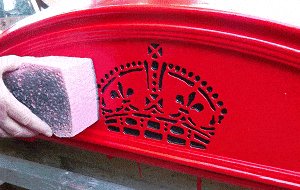
For the crown impressions I just used a water based black gloss.
First Angela painted the crown impressions black. She slopped it everywhere, but it didn’t matter.
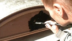
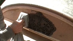
The excess was wiped off with a rag wrapped around a firm pad and white undercoat paint rolled over the top with a smooth (non fluffy) roller.
The rest of the undercoating was pretty much standard stuff.
Chapter 2: The Body Frame
Overview of the body frame
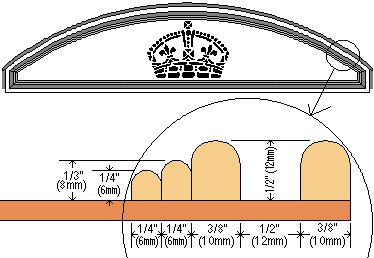
The K2 is adorned with a few decorative corrugated type trims that run around the outside of the frame.
Because I was unable to source any such lookalike wood, I shaped my own out of 2″ x 4″ (100mm x 50mm).
I was able to make the ‘corrugated’ frame members using just a standard circular saw, a planer, and sand paper.
The rest of the material required for the body frame was easy enough to obtain from building supply stores.
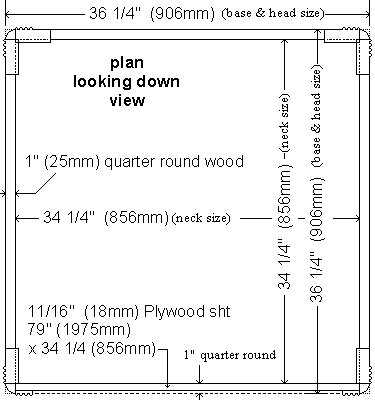
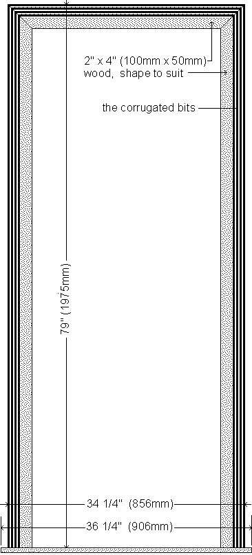
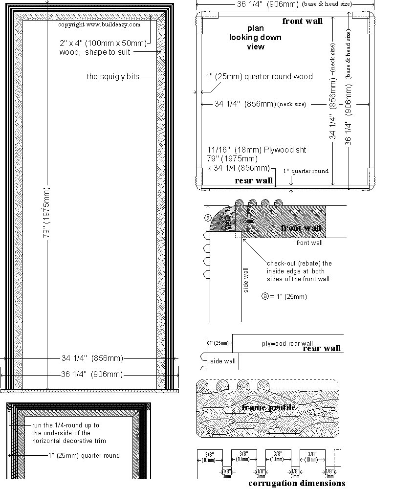
In all, the body frame consisted of 2″x4″ (100mm x 50mm) wood for the framing members (the pieces with the corrugated bits), 11/16″ (18mm) plywood for the floor and back wall, and some quarter-round for up the corners and around the top.
Wood I purchased for the body frame
● 1½” x 3½” (90mm x 45mm): 10 pieces @ 80″ (2m)
● 1″ (25mm( 1/4 round: 4 @ 80″ (2m) and 4 @ 40″ (1m).
● 11/16″ (18mm) plywood: 1 piece @ 36 1/4″ (906mm) square, and 1 piece @ 34 1/4″ x 79″ (856mm x 1975mm)
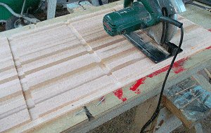
Step 2.1. Shaping the frame members
The frame pieces for the telephone box body were made out of 2″ x 4″ (100mm x 50mm) wood.
The actual or true size of the above mentioned wood was really 1½” x 3½” (90mm x 45mm) because it was dressed (smoothed, planed, surfaced).
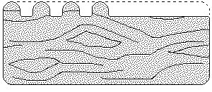
However, the frame pieces had to be shaped to incorporate a decorative ‘corrugated’ bit. In short, they had to be shaped as shown in the drawings below – the before and after drawings.
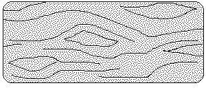
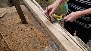
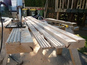
Out of 2″ x 4″ (100mm x 50mm) lumber we shaped frame pieces using a circular power saw, an electric hand planer, and sand paper.
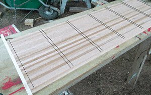
First we marked where to cut the grooves on all of the frame pieces.
We marked and grooved 10 pieces of 1½” x 3½” (90mm x 45mm) lumber @ 80″ (2m) long.
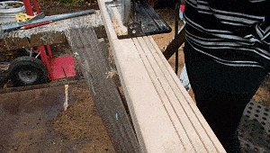
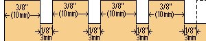
The groove cutting measurements:
There were 4 cuts (grooves). They were 1/8″ (3mm) wide and 1/4″ (6mm) deep.
From the edge inwards, the markings were 3/8″ (10mm), 1/8″ (3mm), 3/8″ (10mm), 1/8″ (3mm),3/8″ (10mm), 1/8″ (3mm), 3/8″ (10mm), and 1/8″ (3mm) – with the 1/8″ (3mm) mark being the cut.
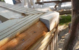
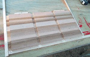
Step 2.1. continued
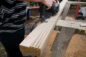
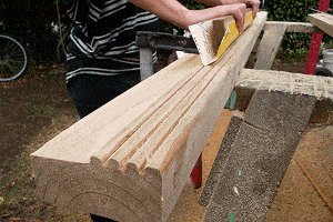
When the groves were cut we planed the adjacent area down to the same depth as the groves with an electric hand planer. It was then just a matter of sanding (and sanding, and sanding) to round the top of the grooves and get the look we wanted.
Alternative tools and cutting methods: We shaped the frame pieces using a circular power saw, an electric hand planer, and sand paper.
Alternative suggestions. A bench saw would have made it easier to cut the grooves which could have been made wider by double cutting. Also a bench saw could have cut the portion that for us needed three or four runs of the electric hand planer to achieve the same result.
A router could have been used to round the tops of the grooves, saving on a lot sanding.
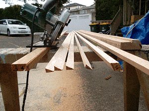
Step 2.2. Cutting the frame members to length
When all the framing members were shaped (corrugated bits and all) they were cut to length as follows:
● 6 @ 79″ (1975mm) with a 45° angle at one end.
● 3 @ 34¼” (856mm) with a 45° angle at both ends.
Note: There were still some pieces of shaped wood left over. They were used at a later stage.
Also the 11/16″ (18mm) plywood for the floor and back wall.
● 1 piece @ 36¼” (906mm) square
● 1 piece @ 34¼” x 79″ (856mm x 1975mm)
Step 2.3. Making the wall frames
I began by making up each individual wall frame.
Using the ‘shaped’ framing lumber (the wood with the corrugated bits) I made three identical wall frames: the front wall frame and the two side wall frames.
Each wall frame consisted of two vertical side members (studs) and a horizontal head. The lengths are given on the previous page.
I made up the wall frames on a flat surface.
It was just a matter of gluing and screwing the head piece to the two side pieces (studs).
I fixed two temporary plywood spreaders to the side studs to keep them parallel.
Each spreader was about 30″ (900mm) long x 12″ (300mm) wide. One was fixed near the top and one was fixed near the bottom.
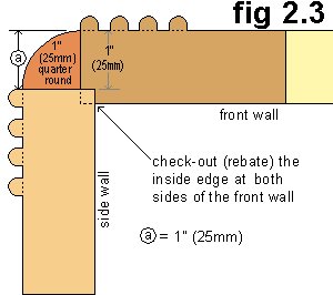
On the front wall only, I had to rebate the inside-edge corners (vertically) on both sides of the wall. This was so that the front and side walls aligned to accommodate the 1″ (25mm) quarter-round pieces of wood that ran the length of the walls vertically.
Refer to the drawing fig 2.3 for details of the rebate size.
My rebate cut was 1/2″ (12mm) in x 1/2″ (12mm) deep, however your rebate cut might be a different size.
It depends on the actual thickness of the frame.
The drawing (fig 2.3) shows that (a)=1″ (25mm).
Using that formula, you will be able to work out the required rebate size.
I made the rebate down each side of the front wall frame with a circular power saw by setting the blade to the required depth and making one cut in along the back, and another cut in along the edge.
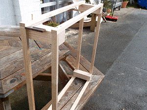
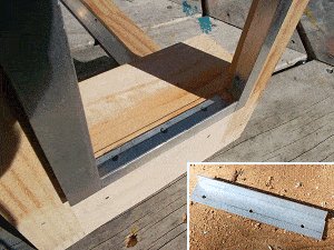
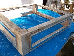
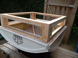
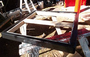
Step 2.4. The body frame
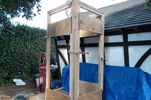
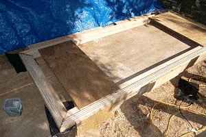
When the individual wall frames were made (the two side walls and the front wall) I stood them up and joined them together.
The two side wall frames fitted into the rebates in the front wall frame.
I held the wall frames together with clamps.
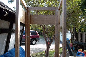
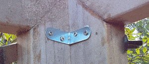
I fixed the frames together on the inside with 4 angle brackets at each corner.
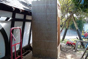
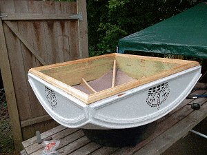
The plywood sheet for the back wall was 11/16″ (18mm) thick, 34¼” (856mm) wide, and 79″ (1975mm) high.
The sides of the plywood sheet were set back from the corners 1″ (25mm) plus the thickness of the ‘corrugated’ bit. (See drawing fig 2.4.1).
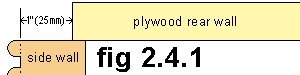
I glued and nailed the plywood sheet to the two side walls.
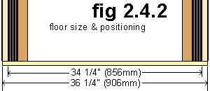
Time to fix the floor: I lay the unit down on its front, fixed the plywood floor to the underside of the studs with glue and screws (see drawing fig 2.4.2), and left the unit lying down in that position awaiting the next step.
Step 2.4. continued
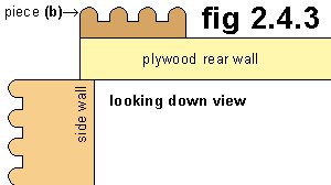
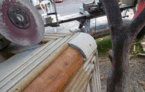
From the leftover lengths of the shaped framing wood (the pieces with the corrugated bits) that I had already made, I had to extract the corrugated bits from the frame pieces in order to use them as the decorative trim around the plywood rear wall.
See piece (b), fig 2.4.3.
I cut the corrugated bits out of the frame pieces just by making two cuts with my circular power saw.
It would have been a little easier to have used a bench saw, but because I was orchestrating the whole project outdoors it suited me better to use few tools as possible most of the time. (You know, in case the rain came down and I had to scarper inside with everything.)
Once made, I glued and nailed the corrugated trim to the sides and top of the back plywood wall.
At that stage the unit was lying face down on its belly.
Note about the glue:
The glue I used for pretty much the whole project was a two pot mix epoxy resin. Actually, it was the same stuff that I used for the fiberglassing except that I added a glue powder to it which meant that I could make it any consistency that I wanted (i.e. thick or thin).
I also opted for a epoxy resin undercoat paint for the complete project as well to ensure that all applications would be compatible.
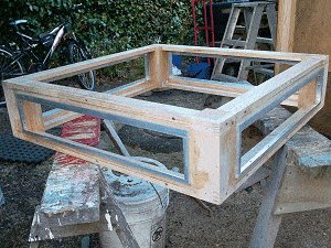
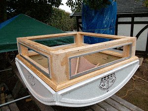
Step 2.4. continued

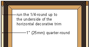
Quarter-round: I cut four pieces of 1″ (25mm) quarter-round wood to the length of 77¼ (1930mm). The length was from the floor to the underside of the top horizontal decorative trim.
I then fixed 1 piece to each corner with glue and nails.
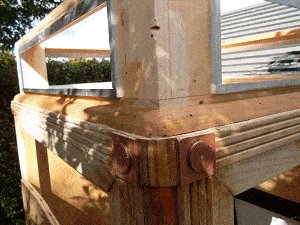
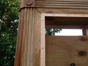
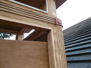
Step 2.5. The shackles
The top shackles comprised of small square pieces of thin plywood, round button pieces (also plywood), and small blocks of wood sanded to a quarter round shape
I cut four 1¼” x 1¼” (30mm x 30mm) pieces of wood into 2″ (50mm) long blocks.
I glued them to the frames above the 1/4 round and held them in place with tape until the glue dried.
Once the glue had dried, I sanded the corner blocks as necessary with an electric rotary sander to make them quarter-round in shape and finishing flush at the sides to the trim (corrugated bits).
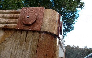
I cut the square pieces for the top corner shackles out of plywood. 8 @ approximately 1¾ x 1¾ (45mm x 45mm).
I cut 8 circles (buttons) out of the plywood 1¼” diameter.
I glued the squares and circles in place and fastened with a small nail through the center of each button.
Chapter 3: The Neck and the Sign
Overview of the Neck
The neck houses the telephone sign.
The neck is what distinguishes the K2 telephone kiosk from the other kiosks as it is the only model with anything that really resembles a neck.
Most of the other models tend to have the head sitting directly on the body with the sign imbedded somewhere in the head.
The head was a relatively simple part of the phone box to make.
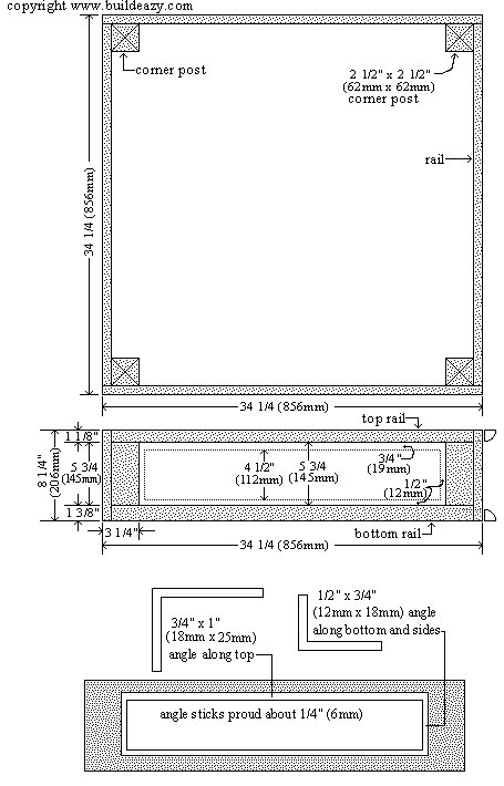
It was basically a box unit that consisted of four frame type side-walls. Each side-wall was made up of top and bottom rails (horizontal members) and corner posts (vertical members).
In between the rails and posts were aluminum angle frames that housed the telephone signs.
The rails of the unit were made out of ¾” (18mm) thick wood which is a common size. The four corner posts were 2 1/2″ x 2 1/2″ (62mm x 62mm). That was a bit harder to source, however it was only a little amount required so was easily made out of a bigger size wood.
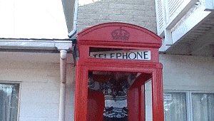
The telephone sign

The telephone signs (four of them) sat in the aluminum angle frame.
What were the signs made of?
Mine were acrylic plastic with the backs frosted (opaque) and ‘telephone’ printed on the front.
At night I wanted inside light to shine through the acrylic thus highlighting the ‘telephone’ print.
There are other options for the sign and I give all the details later on.
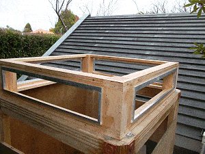
Step 3.1. The neck – making the box unit
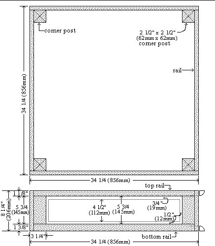
Note: The plan image is scaled to fit in the page.
For a clearer view click on the plan image and it will open in another window where the measurements will be more legible.
Although some plans are shown at appropriate stages throughout the course of these instructions, the plans are also in a complete group in Chapter eight.
The rails
Out of ¾” (19mm) thick boards I ripped (cut lengthwise) two different size strips, 1 1/8;” (28mm) for the top rails and 1 3/8″ (35mm) for the bottom rails.
I ripped enough of each size to allow for the following:
For the top rails I cut 2 @ 34¼” (856mm) and 2 @ 32¾” (820mm).
For the bottom rails, the same – 2 @ 34¼” (856mm) and 2 @ 32¾” (820mm).
The corner posts
I cut four pieces of 2½” x 2½” (62mm x 62mm) wood to the length of 8¼” (206mm).
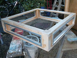
Making up the box unit
I lay two corner posts apart 32¾” (820mm) overall and fixed the top rail to the top and the bottom rail to the bottom, creating an oblong frame 32¾” (820mm) x 8¼” (206mm). Then I made another, two in all.
I stood the above two frames on end and fixed the other appropriate rails (top and bottom) as per picture.
Step 3.1. continued
The corner infill pieces
Next I cut two infill pieces for each corner (to make the corners flush), approximately 5¾” x 2½” (145mm x 62mm) and 5¾” x 3¼” (145mm x 81mm) respectively.
I fixed them in place so that all the corners were solid and flush.
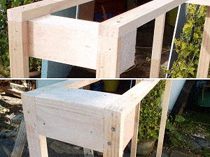
Step 3.2. The aluminum angle for the sign
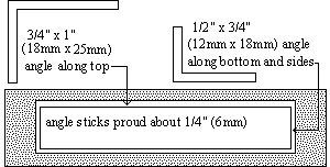
I fixed aluminum angle around the openings.I used ¾” x 1″ (18mm x 25mm) angle along the top, and ½” x ¾” (12mm x 18mm) angle along the bottom and down the sides.
I pre-drilled screw holes in the longer sides of the angle and screwed them to the sides of the openings.
I made the galvanized angle proud (stick out) from the face of the neck about ¼” (6mm).
Note: It is the narrower side of the galvanized angle that shows, the wider side is fixed to the sides of the opening.
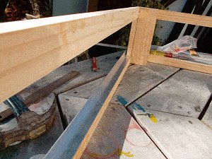
Step 3.3. Internal perimeter pieces
I added (glued and screwed) some ¾” x 1½” (38mm x 18mm) strips of wood around the inner perimeter of the neck. There were 8 pieces in all. They fitted between the corner posts, both top and bottom.
That finished the neck structure.
Step 3.4. Fitting the neck
I turned the telephone box head upside down and supported it on a car tire.
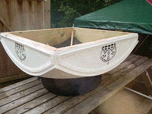
While the head was in that position (upside-down), I took out the inner support structure leaving just the ribs running across the underside of the roof. I also added some glue to the corners where the rib ends touched the sides, just for a bit of added support for the ribs.
I then sat and positioned the neck on the underside of the head and marked around it in readiness for some scotia around the bottom of the neck.
Step 3.4. continued
When I had marked the position of the neck on the underside of the head (it was all upside down at that stage), I took the neck off and fixed (glued and nailed) the scotia to the head slightly away from the position marks. That was to ensure that the neck would have a bit of play inside the scotia i.e. the head was not a tight fit.
It’s very important that I allowed a little bit of play. I wanted the neck to be able to slip easily into place.
Having fixed the scotia, I placed the neck on the head to ensure that it fitted easily.
I removed the neck from the head and positioned it on top of the body.
There I fixed it permanently in place and ran 1″ (25mm) quarter-round wood around the neck, fixing it with glue and nails to both the neck and the body.
Step 3.5. The telephone sign

For the telephone signs I used ¼” (6mm) thick clear acrylic sheet (plastic glass).
The size of each piece (4 pieces in all) was 27¾” (695mm) long x 5 3/8″ (135mm) wide.
I had a sign-writer frost the back and put the ‘TELEPHONE’ text on the front of each piece. My objective was to have a sign that would allow light to shine through, similar to the real thing.
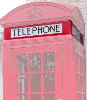
The font

After much research, we (me and the sign-writer) could not find a match from known fonts (within a database of thousands) for the original K2 telephone sign so we made our own hybrid font to match the original.
By the way, after looking at many photos of the K2 telephone box signs it appeared that there were two versions of fonts used, with the main difference between the two being the shape of the letter “O”.
One version showed a more oval (egg-shaped) “O” and the other version showed a circular “O”. See the two different versions in the image.
I went for the latter, circular “O” which also seemed more popular.
Alternatives

I have made a full-size printout version of the K2 telephone sign. The sign is 3 pages in a PDF file. The pages overlap each other so they will need to be cut to suit.
If you print the file out, be sure to have your printer page handling options set to 100% or Page Scaling: None.
There are a number of ideas that you can do with the printouts if you do not want to go to the expense of using a sign-writer.
For inside use you can simply glue the printout to cardboard or wood-board.
For outside use: same as above but maybe laminate the signs, or frame them behind glass.
You can get the downloadable printout file in chapter eight
Chapter 4: The Door and Windows
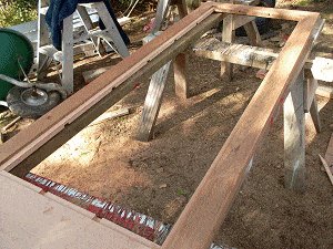
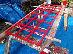
Step 4.1. The trim around the door and window openings

Before I started on the door and windows, I prepared the door and window openings (in the main body frame) by running a trim around the edges.
It was the last bit of wood required to finish the body.
I ripped down some triangular strips for around the door and window openings and fixed them with glue and nails.
All in all about 50ft (15m) including waste. See the pictures below.
Door and window overview and plan
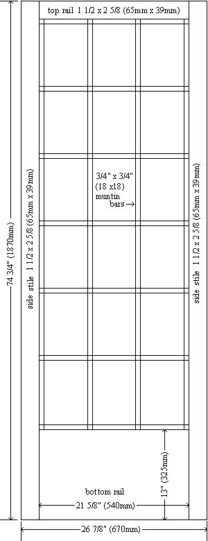
The door and two windows were identical in make although the door was about 5/8″ (15mm) narrower than the windows as it had to have clearance to open and close.
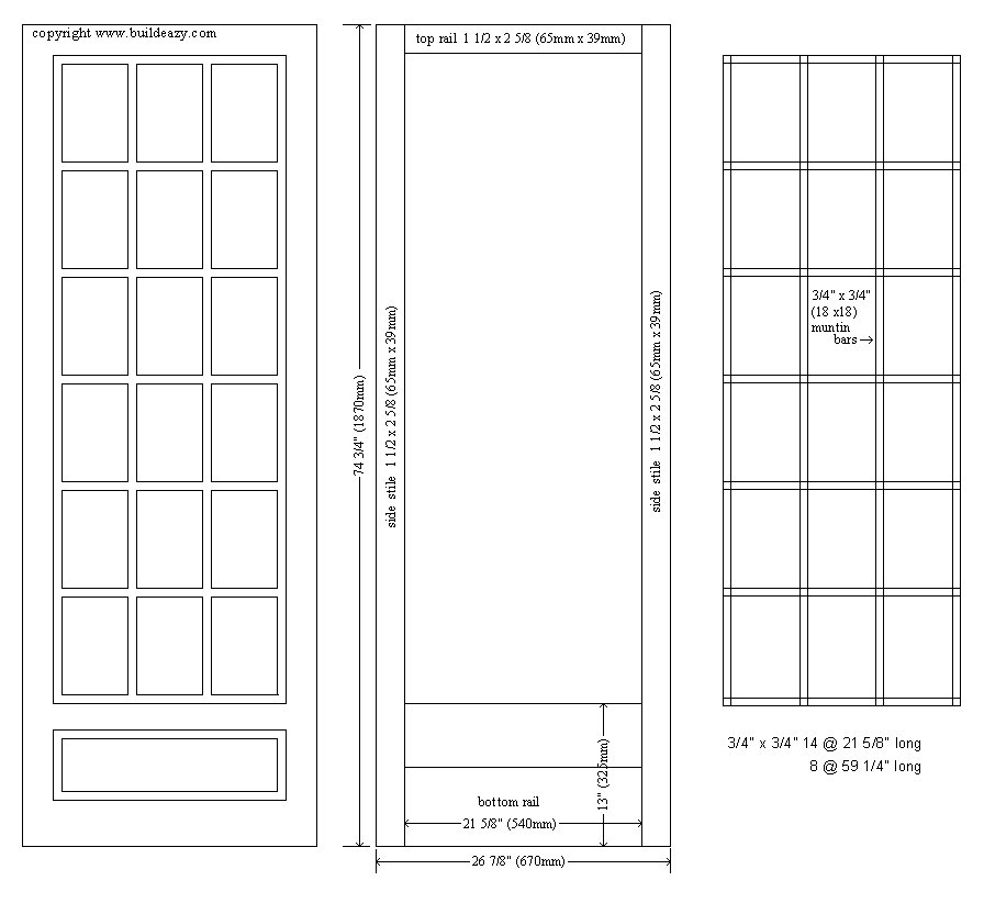
The door/windows were constructed out of 1 1/2″ x 2 5/8″ (65mm x 39mm) cedar for the side stiles (the vertical sides members) and the top rails (the horizontal top member).
The bottom rails were made out 1½” x 7¼” (180mm x 39m) cedar joined together to make the required width.
The muntin bars (grilles, grid) were of 3/4″ x 3/4″ (18mm x18mm) cedar.
There were two grids of muntins per door/window. A sheet of acrylic was sandwiched between the two grids.
Note: If you are making this door or window, use the measurements as a guide only, as the wood that you use may differ in size along with other inconsistencies.
Check all measurements on site.
The imperial measurements given are not an exact match for the metric measurements. Use one or the other but don’t mix and match. For the most part 1″ is translated into 25mm for rounding off purposes. In other words, a telephone box made using the imperial dimensions will be slightly bigger that if you use the metric dimensions. About 1.6% or so. Not really worth worrying about.
Step 4.2. Wood for the door and windows
I bought the following wood for the door and two windows:
● 13½ft (4m) of 1½” x 7¼” (180mm x 39m) cedar for the bottom rails
● 47ft (14m) of 1½” x 2 5/8″ (65mm x 39mm) cedar for the top rails and side stiles.
● and 110ft (33m) of 1½” x ¾” (40mm x 18mm) cedar for the muntin bars.
I ripped the latter in half to make ¾” x ¾” (18mm x 18mm) muntin bars (to make up the grids).
Cutting the side stiles
The side stiles are the vertical members of the door and windows.
Out of 1½” x 2 5/8″ (65mm x 39mm) cedar, I cut 6 pieces @ 74¾” (1870mm) long. Two for each door/window unit.
Cutting the top rails
The top rail is the horizontal member at the top of the door/window.
Out of 1½” x 2 5/8″ (65mm x 39mm) cedar I cut 3 pieces @ 21 5/8″;” (540mm) long: one for each door/window unit.
Cutting the bottom rails
The bottom rail is the horizontal member at the bottom of the door/window.
Out of 1½” x 7½” (180mm x 39m) cedar, I cut 6 pieces @ 21 5/8″;” (540mm) long: two for each door/window unit.
The bottom rail needed to be 13″ (325mm) wide. To achieve that width I joined two pieces of 1½” x 7¼” (180mm x 39m) cedar together and cut off the excess to form 1 piece that was the required width.
Cutting the muntin bars
The muntin bars are the strips of wood that make up the grille (grid).
Out of ¾” x ¾” (18mm x 18mm) cedar, I cut 42 pieces @ 21 5/8″;” (540mm) long and 24 pieces @ 59¼” (1480mm) long.
That was the amount for 6 grids, two for each door/window.
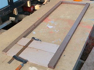
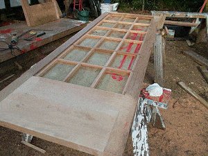
Step 4.3. Joining the stiles and rails
I cut the stiles and top and bottom rails. For the bottom rails I joined two pieces together and cut off the excess to achieve a width of 13″ (325mm).
I then glued and nailed the side stiles to the top and bottom rails. I made up three units in all.
Step 4.4. Notching the muntin bars
I cut all the ¾” x ¾” (18mm x 18mm) cedar muntin bars to length.
42 pieces @ 21 5/8″ (540mm) long and 24 pieces @ 59¼” (1480mm) long, enough to make 6 grids – two for each door and window unit.
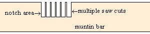
The muntin bars needed to be notched (channelled out) at various intervals so that the notches in the vertical muntin bars would slot into the notches in the horizontal muntin bars and form a rectangular grid approximately 21 5/8″ (540mm) x 59¼” (1480mm).
The notches needed to be the width of a muntin bar and 50% of the depth.
I lay groups of muntin bars side by side.
I marked where to cut the notches along the muntin bars.
The vertical muntin bars needed seven notches spread evenly along the length.
The horizontal muntin bars needed four notches spread evenly along the length.
I then set the blade on my circular power saw to a depth of 50% the thickness of a muntin bar.
I made multiple saw cuts along each of the marked areas and then cleaned the notches out with a sharp chisel.
By doing this I was able to notch out multiple muntin bars at one time.
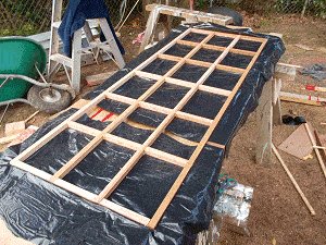
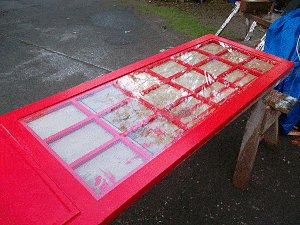
Step 4.5. Fixing the muntin bars
I lay one of the door/window units flat on a working platform.
I marked around the inside of the frames 10mm up from the bottom.
I fixed muntin bars around the inside of the frames on that mark, i.e. the muntin bars were 10mm up from the bottom.
The side (vertical) muntins had the notches facing down, and the top and bottom (horizontal) muntins had the notches facing up.
I cut a 3/4″ (18mm) plywood platform slightly smaller than the size of the muntin grid area, say approximately 21½” (537mm) x 59″ (1475mm).
I placed the platform in the opening underneath the muntin bars so that the muntin bars were sitting on the platform.
I joined (with glue) the rest of the muntin bars (both vertical and horizontal) required to make up a complete grid.
The notches in the horizontal muntins slotted into the notches in the vertical muntins.
I then made up a second grid and sat it on top of the first grid with no nailing whatsoever, just plenty of glue in the notches where the muntin bars joined.
I separated the two grids with some plastic so that the two freshly glued muntin grids wouldn’t stick to one another.
That was the bits and pieces for one door/window unit taken care of.
I then did the same for the other two.
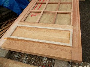
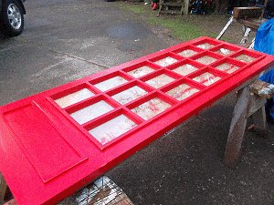
Once the glue was dry, I lifted out the top grid (from each door/window), removed the plastic, and fixed decorative squares to the bottom rails.
The squares were made out of ½” x ¾” (18mm x 12mm) cedar wood.
The squares were 21 5/8″ (540mm) x 7″ (175mm). They were positioned 2 3/8″ (60mm) down from the grid.
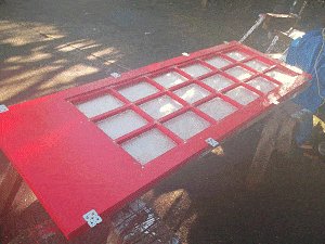
Step 4.6. Painting the door and windows
At this stage the door, windows and grids had to be painted prior to fitting the acrylic sheet (plastic glass).
With a craft knife and a chisel, I cleaned off all the excess hardened glue and then I gave everything a good sanding.
I gave the door, windows, and associated grids three coats of paint – an undercoat and two over coats.
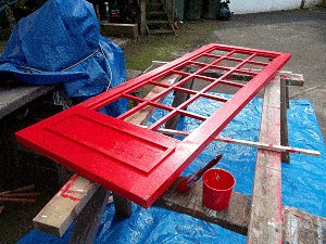
For the undercoat I used a white two pot epoxy resin undercoat paint.
For the main coats I used a water based paint: I wanted something that would dry reasonably fast to shorten the time between final coats.
The red color was BS 539.
Step 4.7. The acrylic sheet
For the door and the two windows I used 3/16″ (4.5mm) thick acrylic sheet: 1 @ 21 5/8″ x 60″ (540m x 1500mm) and 2 @ 22″ x 60″ (550mm x 1500mm) respectively.
Note: Acrylic sheeting is widely known as Plexiglass. Plexiglass, however, is the name given to acrylic sheeting manufactured by Atofina. The same acrylic type sheeting is also known by the names Acrylite, Lucite and Perspex. I’ll refer to it simply as acrylic sheet.
I laid each door and window unit face up on a flat work surface.
To each door and window unit I placed an acrylic sheet on top of its fixed grid.
I then placed a second grid on top of that, so each acrylic sheet was sandwiched between two grids.
I turned the units over on a packing piece to keep the weight on the grids.
I drilled through the top grid and the acrylic sheet.
I made the drill size bigger than the screw shank and honed back the point of the cutting edge of the drill to make it easier to drill through the acrylic sheet.
I screwed the grids (through the acrylic sheet) together.
I then added brackets to the sides of the window frames, four each side.
This would make it easy to fix the windows to the telephone box.
Chapter 5: The Base and Some Painting
Step 5.1. Making the base
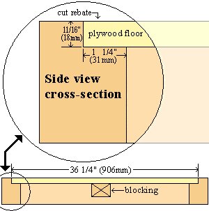
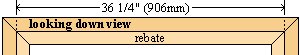
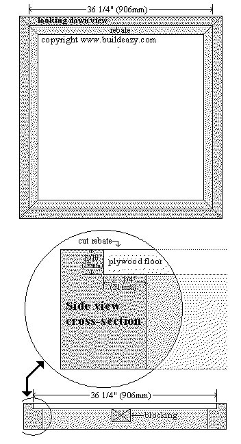
The base is simply a square frame with a rebate cut around the inside edge in which the plywood floor sits.
I cut four pieces of 2½” x 3½” (90mm x 95mm) wood to the length of 40″ (1000mm).
I marked along the narrow face of each piece 1¼” (31mm) in, and along the adjacent face 11/16″ (18mm) down (the thickness of the plywood floor).
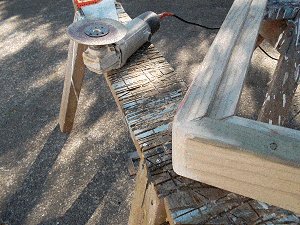
I set the blade depth on the circular saw to the appropriate depth and cut along the marks creating a rebate 1¼” (31mm) in and 11/16″ (18mm) deep.
I cut a 45 degree miter (angle cut) each end of each piece across the narrow face of the wood angling in towards the rebate.
I made the cuts so that the length between the longest points of the rebates was 36¼” (906mm).
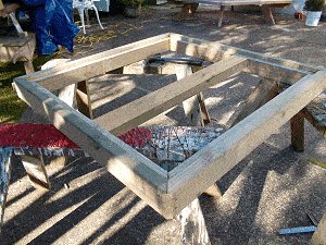
I fixed the four pieces together to make a square.
I rounded all the corners with a disc sander.
And finally (as far as construction went) I added a piece of wood (blocking) across the middle. The purpose of that was to take any bounce or spring out of the plywood floor.
Step 5.2. Some painting
I used a two pot epoxy resin white undercoat paint as that worked for the wood, fiberglass, and the aluminum. The red color was a semi-gloss water paint – BS 539. The black for the base and crown impressions was a gloss water paint, as was the grey for the telephone box floor. I under coated everything once and applied two top coats.
Note: The same safety rules apply to the epoxy resin paint as with the epoxy resin used for the fiberglass.
When the red paint on the head dried, I slopped black paint in (and around) the crown impressions and immediately wiped off the excess with a firm damp sponge.
Chapter 6: Putting it all together
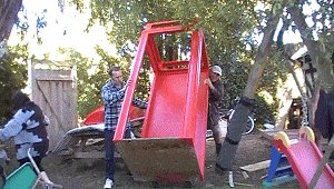
Step 6.1. Putting it all together
This is the bit we were waiting for.
All hands on deck: the most exciting part of the whole project. We were finally about to get a look at the phone box in its entirety ( the exterior, anyway).
Santi (son-in-law) and I placed the door-less and window-less telephone box body on a hand truck and shuffled it pretty close to the position it was earmarked to go.
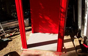
We put the base in place and lifted the telephone box body into that.
The plywood floor dropped neatly into the rebated edges of the base.
The top of the plywood floor finished flush with the top of the base.
We moved a picnic table as close as we could to the front of the phone box and then ran a couple of planks around the sides.
That was our scaffold to stand on to lift the head onto the neck.
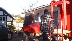
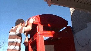
So up we went, onto the picnic table with the head of the telephone box in our hands.
Heave ho! over the top and down onto the neck.
The scotia around the bottom of the head slipped neatly over the top of the neck. Perfect fit.
In with the telephone signs.
Angela ran a bead of clear adhesive type silicon around the edges of the aluminum housing and popped the signs into place.
They were held there with a couple of ‘L’ clips, pushing against the edges of the signs and fixed to the sides of the openings.
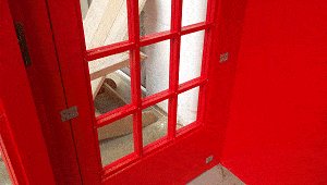
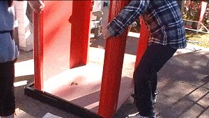
The widow units slotted into the appropriate openings and were fixed to the side studs with screws through the brackets (that had previously been fitted to the window units when they were made).
The window went in very fast.
The door took a little bit longer to hang in place.
It was just hung like a typical door with three hinges – one top and bottom and one in the middle.
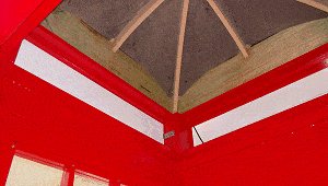
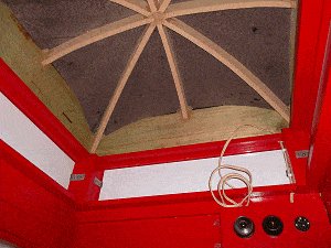
The photo gives a look at the underside of the roof with the ribs running across from side to side.
Everything seemed to go according to plan.
All in all we were pretty pleased with it, and so were the passersby, most of who didn’t hesitate to come in and show their interest.
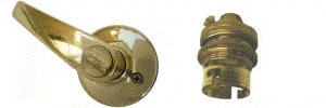
And then came Angela to put on the door handle.
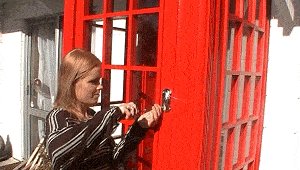
The door handle was a replica of the real thing.
Tony Inglis who owns the website http://www.unicornkiosks.com/ was kind enough to send it over from UK for free.
I guess it doesn’t get any cheaper than that–thanks, Tony!
Some strengthening and the door closer
Some strengthening

I fitted two 10″ (250mm) galvanized angle brackets to the front wall, one each side at the inside top corners.
That would help stop any sideways warp.
On the side where the door closed I ran a piece of 3/16″ (4mm) thick x 1 3/8″ (40mm) wide aluminum strap down the inside of the door stud, fixed half on and half off.
The protruding half (the half off bit) acted as a door stop.
I also fixed a thin galvanized plate to each top corner of the side walls for added strength – once painted red they wouldn’t be noticed.
The door closer
The fly-screen door (on the front door of our house) had an old style door closer on it – a spring/cushion type.
Needless to say, I took it off and fitted it to the telephone box door.
Uh-oh. That didn’t go down too well with my dear wife.
I don’t think some women understand the psyche of a DIYer on a mission. If he spots a part he needs he will grab it regardless of what it is doing or holding up.
I vaguely remember hearing the words, “if you like the telephone box so much – go and sleep in it.”
Anyway, it only took a month and a new fly-screen door for things to get back to normal around the household.
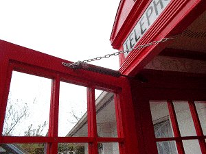
Meanwhile, back to the job. I also fixed a chain to the top of the door to stop the door from opening too far and putting undue pressure on the door closer, as I knew that the grandkids and their friends would be in and out of the phone box like a dog at a fair, and that the door would get more than its share of punishment.
Chapter 7: The ceiling and the night light
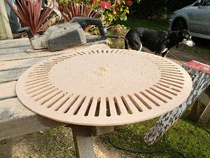
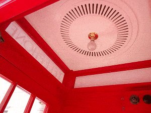
The desired effect
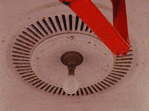
This is the picture of the ceiling that I wanted to emulate for my phone box.
I searched various stores for parts that may have helped me to put together a similar ceiling.
I looked in shops that sold plaster, fiberglass, and wood ceiling roses but to no avail.
I even looked in car wheel shops thinking that I may have come across a hubcap with a similar pattern (the rose in the photo reminded me of a hubcap).
Also to no avail.
Once again I ended up making my own.
Step 7.1. The rose and ceiling
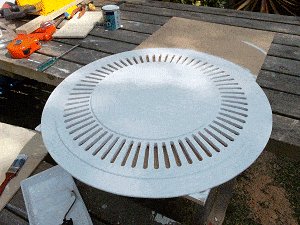
The rose is the fancy circle piece that is in the center of the ceiling. The light fitting is fixed to the middle of the rose.
The wood: To make the rose I used two pieces of 1/2″ (12mm) mdf custom board 24′ x 24″ (600mm x 600mm)
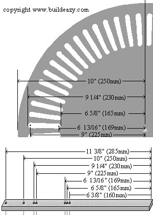
One piece was used to cut out the main circle which was 20″ (500mm) diameter. The other piece was used to cut out two circle pieces 6 3/8″ (160mm) diameter and one ring piece 2 1/2″ (55mm) wide with a diameter of 22 3/8″ (570mm).
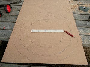
Making the rose pattern
To mark out all the circumferences I made a compass in the form of a strip of wood with 7 holes drilled along it. Each hole represented a center point for a particular circumference.
The piece of wood that I used to make the compass was a piece of 1″ (25mm) wide x 1/4″ (6mm) thick strip of wood 12″ (300mm) long.
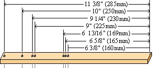
By sticking a nail through one of the holes in the compass (the strip of wood) and tapping it (the nail) a little way into the mdf board, a required circumference could be drawn by holding a pencil at the end of the wood and turning it in a circle using the nail as the axis point.
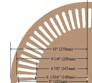
For the main circle piece I drew 5 circles, each with the following radius:
● The circle with the 10″ (250mm) radius marked the edge of the main circle piece: the cut-off line.
● The circle with the 9 1/4″ (230mm) radius marked the ends of the slots.
● The circle with the 9″ (225mm) radius marked the points for drilling at the end of the slots where the circle line crossed the radius lines.
● The circle with the 6 13/16″ (169mm) radius marked the points for drilling at the beginning of the slots where the circle line crossed the radius lines.
● The circle with the 6 5/8″ (165mm) radius marked the beginning of the slots.
Marking, drilling, and cutting the rose
Then I drew 32 straight lines (diameters), evenly spread running from one side of the circle to the other side, passing through the center point.
I began by drawing two diameters at right angles to one another. Then I drew another two in the middle of those, making 4 diameter lines.
Then I drew another 4 in the middle of those, making 8 evenly spaced diameter lines.
Then I drew another 8 in the middle of those, making 16 evenly spaced diameter lines.
Then I drew another 16 in the middle of those, making 32 evenly spaced diameter lines. And that was enough. That meant that there were 64 evenly spaced lines (radii) running from the center to the edge of the circle (circumference).
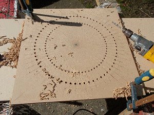
The circle with the 9″ (225mm) radius and the circle with the 6 13/16″ (169mm) radius marked the drilling points where they crossed the radius lines.
At those points I made an indent in the MDF board with a center punch, giving a starting guide for the drill bit.
I used a 3/8″ (10mm) drill bit for the 64 outer holes and a 5/16″ (8mm) drill bit for the 64 inner (closest to the center) holes.
Each pair of holes along the radius lines marked the length and width of a slot (yet to be cut).
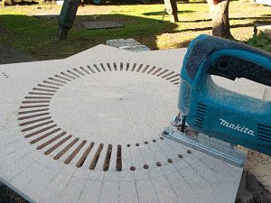
I joined the outside edges of each pair of holes with a couple of straight lines.
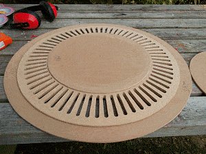
I cut along those lines with a jig-saw creating a slot.
And so on and so on until all 64 slots were cut.

Tapering the rose
I wanted to make a tapered edge around the slotted circle piece so I made a makeshift set-up.
I pinned the piece (through the center) to the corner of a work table slightly overhanging.
My wife Jenny turned the circle around with her hands while I held the electric planner on the rim (not near her hands) until I achieved the desired result.

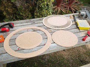
On another piece of board: using my compass (strip of wood with the holes in it) I marked two circle pieces 6 3/8″ (160mm) diameter and one ring piece 2 1/2″ (55mm) wide with a diameter of 22 3/8″ (570mm).
I then cut them out with a jig-saw.
Three circles in all – two solid circles and one ring circle.
Once all the circle pieces were cut I glued them together.
Painting and fitting the ceiling and rose
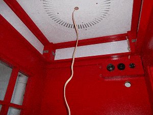
For the ceiling board I used a piece of 1/2″ (12mm) particle board 32″ x 32″ (800mm x 800mm). I cut the board in half, for ease of installation.
I painted the ceiling and the rose all white except for the circle on the ceiling where the rose was to be fixed. That was so there would be a better effect when looking into the slots in the rose.
I ran electric light wire into a corner of the cavity in the head.
I also made a little electrical box that contained a light switch, a power outlet and a plug for incoming power.
I cut a little round hole in the back wall just below the electrical box so that I could run a power lead from the house to the electrical box.
I drilled a hole through the center of the ceiling and the center of the rose for the electric light wire.
I threaded the light wire through the hole in one of the ceiling boards then sat the two ceiling boards on the ledge around the top of the neck.
The wire was then threaded through the hole in the rose, which was then screwed to the ceiling boards.
The light goes on
I couldn’t source a brass light fitting that looked like the real thing so I made my own out of a brass table lamp socket and the back plate off a brass door handle.
Dusk came, and one of the grandkids had the privilege of turning on the light for the first time.
A satisfying moment.
We will eventually get a working authentic looking telephone with an A and B push button coin box, but for the time being, the status quo is pretty good.
A project well worth the making.
The plans


Hi,
thought I’d send you a picture of my attempt at your plans for the K2 Telephone Box.
I’m not quite finished – still got the ceiling, light fitting etc.
Regards, Dave McKay
G’day Les
Its great to have friends working at the right places. Saved me many hours of work.
Really enjoying the challenge of building the phone box.
The cost of cedar in NZ is really expensive
Kind regards
Doug Taylor
Thanks for your plans which are great. I am making good progress. Roof next! Cheers
Derek Forbes
l have built a k2 phone box following buildeazy plans. With a few minor changes to the way of doing things. I am very pleased with the results , and everyone who sees it ,or sees my pics are really impressed. Thank you so much for your inspiration !
The only real problem is , that it has not stopped raining since I finished and I am getting leaks which I believe are somewhere on the neck.
I recycled materials as far as possible ,to save money.
These are the changes I made to either save money or make easier.
I cast the roof in a mix of sharp sand , polystyrene balls ( beanbag fill ) and cement.
I made the brass lamp holder out of an old wall light.
The door handle was bought from Wilkinsons for less than £2 and I added a stainless plate to the back of it.
I tried to route out the crowns but kept messing up. So I finished up making stencils to paint them on.
I printed the signs and sandwiched them between glass.
I enclose pics for your approval.
Tom Wright
I ordered your plans for the Red English K2 Telephone Box.
After reviewing them I decided to go off on my own and downsize the project for the purpose of making a novelty lamp.
I encorporated some elements of your design and some from the various models of the K series boxes.
Enclosed is a picture of the final product.
It stands just under 5′ tall, 21″ wide and 18″ deep.
Hi. Here is a couple of photos of the k2 telephone box I made from you plans.
The only change I made was to use mesh and fibreglass only for the dome and to put a concrete slab within the base to give it some stability outside.
This just made it easier for me to complete it on my own.
It is the very first project I have tried with wood and your plans were easy to follow (although with no joinery knowledge it took quite a long time to complete) and I have now bought the tardis plans for my next project.
Thanks
Andy from Carlisle in Cumbria, UK
Hello Les,
Thanks for all the inspiring stuff on your website – too many projects for the future!
I’m a brit who’s been in Melbourne a couple of years and has now married an Aussie. To add a touch of Britishness to a very Aussie, country wedding… my friend Mark – a fellow Pom – and I took on the challenge of the K2 Phone Box, with the intention of making it a photo booth at the wedding.
Plenty of challenges on the way, often as a result of only being able to purchase wood in standard aussie metric dimensions, and then adjust everything accordingly. Others caused by our complete lack of wood-working experience.
We made a few minor adjustments:
– Reduced the amount of curved decoration on the head, due to lack of skill and patience on our part!
– Slightly reduced decoration of top corners of frames, again due to lack of time.
– Added a door latch, carpet on the floor, corner brace brackets to the base/frames, included a handle inside and out.
– Added full height internal supports on the inside of each corner to better hold the head up. This was just because we were incredibly nervous about the very heavy head being held by such little contact, and we were going to be opening our doors to drunk people so wanted to avoid the possibility of disaster!
– There were other things we had to do because we had to build it in such a way that it was easily packed down, transported and re-constructed, and would continue to be after the wedding.
(We also went for a plain ceiling due to lack of time, and patience.)
Anyway, we thought you’d like to see the end result. It went down very well on the day, and helped stop me being completely upstaged by my wife making her own (amazing) wedding dress.
https://www.facebook.com/media/set/?set=a.10153532545255099.1073741827.822940098&type=1&l=234e883bae
Best,
Tim Pyke
More k2 photos as promised from
Pete steers. Kereru road. Hastings. Hawkes bay. New Zealand.
I would like to comment on this quality content. I can see you have done a lot of homework and given this topic much thought.
It’s incredible, is so beauty! With patient y will do it, thanks for all, without this pages I can’t think to do it, thank you again. Leo.
Excellent! A fabulous project, well executed and very well explained here. I particularly liked the use of hypertufa in the roof construction. The attention to details is inspirational. I’ve really enjoyed reading how you made this. Thanks!
New Zealand. Hawkes bay. May 2013 and finally finished the K4 phone box. Sprayed all surfaces and obtained a 1950s Bakelite phone, working, and had a phone box party. Came out well in the end.
Yvonne Steers
It would be awesome if you would build the Dr. Who Tardis! It would probably be similar to your red telephone box. If you could do the plans to build one step by step, that would be so cool. The Tardis would be a popular DIY plan to build.
I hope you would consider it!
Thank you for your inspiration
John R
I have completed my phone box project. Well not really, I am enhancing the interior with some 40’s- 50’s period signs, an AB box, and a phone.
I truly enjoyed this project, it pushed my skills at times and that was a good thing as I learned a lot.
I have attached some photo’s for you to look at. Thanks Again
John R
Nice! I want one.
Albert, Kentucky
I would like to give you much praise. Y did a beautiful job and created a masterpiece.
I am building one also. Mine is more like the k6 and will be only 7 feet tall. It will be inside my home and will serve as a elevator car traveling only one story.
I cannot find a paint dealer that can provide the color BS 539. Any ideas of where to get it? Again– Congrats on a great example of a Telephone kiosk.
Billie Sims
I looked over the web site but was not able to find an answer to this question. I would like to know what the final, approximate, total weight is using your plans and suggested materials. Thanks in advance All the best,
Reply from Les
Hi Ron Actually, I have no idea. Two of us could lift the head up and on and that was the heaviest part so if I had to make a rough guess I would say all up around 200kg (440lb). At the time of writing this I am out of the country but when I get back in a few weeks I will try and weigh it.
Ron – Oregon, USA
Hope a Tardis project gets under way Les. Could be much the same as the red phone box I guess.
Pete Steers
Hi, i see you have used cedar in the doors. wondering what type of timber you used in the rest of the phone booth. regards alan7.
Alan
A very good likeness, very well done.
The only thing that I could say is that as far as I can remember, the glass was held in the frames by I think brass rivets. The door closure was a pressure one and not a chain. Apart from that well done.
Ralph
Congratulations! A beautiful job.
I’d like you to create plans for a T.A.R.D.I.S. lol
What a great challenge. Just got started. One section at a time makes the wallet and wife happier. Based in New Zealand wood is SO!dear to buy. Got my dome complete and the neck. Onto the frame now while the dome finishes drying. I wonder what the average amount of hours these take to build?
Reply from Les
It does take a long time to make and it will keep your wallet empty, but it will be well worth it. Everyone who has seen the one I made has commented on it and wanted one for themselves, more so than any other project I have done.
Pete Steers
I am sending recent pic’s of my phone box project.
I needed to make some adjustments due to the fact that mine will be indoors and I must do the building in my workshop and assembly in the room where my bar is.
All is going fairly well no major issues. The head is as you planned except I made the dome from 1/8 bendable plywood and am working the seams with Bondo.
I have made the frame, back panel and floor piece but will do the painting in the shop.
I do not have a “death wish” for paint spillage on the carpet.
John
Nice work and documentation. Thanks! Now I build a micro-flash-drive with the use of your ideas.
And what about your next step? What about TARDIS?
This is my micro TARDIS
Wouldn’t it be easier and lighter to carve the dome out of a block of styrofoam? Make a block the height and width of the dome, draw the arcs on each side and start from the top working in all directions to the arc remove foam until you have the final shape. Sand to final shape fill and “oopsies” as need with a plaster filler, prime and paint. If it going to be outdoors you could cover the dome with a fiberglass cloth and resin and then apply the finish color. It may require some sanding of the fiber glass before painting but the finished product would be lighter than the concrete one and easier to work with.
This is my humble opinion and it is just that….an opinion! Thanks for coming back to a newsletter form, not everyone likes or wants to be on F.B. or Twitter.
Gosh that looks good. I’ve seen old phone boxes for sale and they cost hundreds and wouldn’t pay that. I quite fancy one but not sure whereabouts in the garden I’d put it, or what I’d put in it.
I’ve just found your site by accident so will bookmark it and follow your build with interest.
Bill (Liverpool UK)
I can’t wait to see the next post. Thinking ahead to the sides and door. Looks like to foam is the way to go. My booth will be indoors near my English bar .
John R
I started building a K6 model about six years ago but never finished it. I agree with you, I like the k2 model better. You have rekindled my desire to build another and this time maybe finish it. I will follow your progress with interest, and when you have the final plans online, I will more than likely have another go.
Tony, Buffalo NY (ex England)
I shaped one of the decorative frame pieces (as shown on page 8) out of 2×4 using a bench saw and a sander. I achieved the desired look and found it easy enough to do. It was just a practice run to see the outcome. I will make a K2 when your plans are out and my wife has already picked a spot to place it. AS far as I know I will have the only one in Texas.
A. T. Ryan, Austin, TX
Hi.
This is my RED TELEPHONE BOX. Material = cca (approximately) 100Ł. Working hours = cca (approximately) 30. Head and neck is from polystyrene, body is from thin wood.
Hi there, first of all, congratulations for that amazing work. How are you coming along with the documentation? Would you be so kind to send me a copy of the PDF you made for the crown drawing? Looking forward to it 🙂
When we returned from a year living in England a few years ago, my husband decided we should have a phone booth in our garden in Australia. I searched and searched for plans online, but to no avail. We are finally landscaping out there, and I’m so amazed and pleased you have done all the hard work already! I’m eagerly awaiting the plans!!Thanks!
Sandra, Australia
I’m proud to present you a phone box made in Romania after your great plans maybe you want to use the images on your website.
thank you very much.
Cosmin Radulescu, Romania
I have read and re-read your wonderful plans for the English Phone Booth, Les, and thanked you a thousand times for handing me the dimensions and build ideas.
The attached pictures of my Little Free Library shows it’s approx half scale. I took liberties, many indecent, with your plans, but the Phone Booth DNA is unmistakable.
It was built out of epoxied White Oak, and nary a fastener used until the base. You’re the guy I thank for helping me do it.
BTW – I build outdoors, year long, under a deck, with a table saw I can carry in one hand. It is amazing what you can do with a table saw slide table. I very much appreciated your simple approach to building!
http://westseattleblog.com/2014/10/west-seattles-newest-little-free-library-is-fit-for-a-doctor/
Thanks,
John T. Monahan
My name is Andrea. I like to build things out of wood and I found your website with great projects.
One that stroke me best was the K2 kiosk, that was about a year ago and since I couldn’t stop thinking of when I’ll start doing it. Well, now I’m almost done and looking forward to finish it.
While doing the K2 I was recording all of the steps showing how I made the pieces.
Since I live in Mexico (in a small town) it’s hard to come by things to build, such as exact color BS 539, hardware, epoxy, fiberglass, etc.
So I used many different approaches and techniques to build parts, as they say ”make do”.
Andrea Arzensek
Hi Les and viewers
My phonebox is now taking up pride of place in our back yard..
Rather than build a timber base I have used small plastic 12 mm high blocks to keep the box above the concrete pad and away from water
These are currently used in the house building industry)
The box is strapped to the concrete base (300kgs) using galvanised L brackets
I also made up the exterior corner shakels by bending aluminium to provide added strength.
I did take some artistic licence by routing the exterior muntin bars with a decorative bevel and also tiling the floor.
The tiles form a sill that prevents water from migrating under the sides of the box
On my visit to the UK last year I bought a coin box as I couldn’t locate one anywhere in NZ (Half my baggage allowance)
I copied the internal shelving from pictures
I didn’t router the crowns but used transfers instead. (Done to lessen any water ingression plus the top of mine was fibreglass over solid polystyrene)
To save on the cost of an electrician I have used a 12v system with a 60w bulb
I changed the old phone from pulse to tone using a “Dialgizmo” and it works fine.
I am very pleased with my result and have just downloaded the plans for the Police Box
Thanks for the excellent plans Les. I have enjoyed every minute of the challenge
Regards
Doug Pukekohe
Hello Les,
Thanks for all the inspiring stuff on your website – too many projects for the future!
I’m a brit who’s been in Melbourne a couple of years and has now married an Aussie. To add a touch of Britishness to a very Aussie, country wedding… my friend Mark – a fellow Pom – and I took on the challenge of the K2 Phone Box, with the intention of making it a photo booth at the wedding.
Plenty of challenges on the way, often as a result of only being able to purchase wood in standard aussie metric dimensions, and then adjust everything accordingly. Others caused by our complete lack of wood-working experience.
We made a few minor adjustments:
– Reduced the amount of curved decoration on the head, due to lack of skill and patience on our part!
– Slightly reduced decoration of top corners of frames, again due to lack of time.
– Added a door latch, carpet on the floor, corner brace brackets to the base/frames, included a handle inside and out.
– Added full height internal supports on the inside of each corner to better hold the head up. This was just because we were incredibly nervous about the very heavy head being held by such little contact, and we were going to be opening our doors to drunk people so wanted to avoid the possibility of disaster!
– There were other things we had to do because we had to build it in such a way that it was easily packed down, transported and re-constructed, and would continue to be after the wedding.
(We also went for a plain ceiling due to lack of time, and patience.)
Anyway, we thought you’d like to see the end result. It went down very well on the day, and helped stop me being completely upstaged by my wife making her own (amazing) wedding dress.
Best,
Tim Pyke
Hello!
My name is Evgeny Kochergin. I am from russia. Of your plans, I made several phone booths of the K2 model. The plan is excellent. Everything converges without problems. For me it was difficult to make a frame around the door and I did not find a handle of this shape like yours. In general, I liked everything very much. Thanks for your work!
Just curious what the average cost has been for the telephone box build? Thank you.
Hello from the states! I’m building my wife a phone box display case and would like to use the BS 539 red of course. I cannot find anyone that sells it near me or would be willing to ship from the UK. Any suggestions? TIA